
Page 66 - Parker - Heavy Duty Hydraulic Cylinders
P. 66
Catalog HY08-1114-4/NA Heavy Duty Hydraulic Cylinders
Mounting Information – Large Bore Series 3H
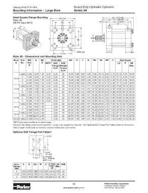
Head Square Flange Mounting E X SQ. Z B + S T R O K E
Style JB T E Y P + S T R O K E
(NFPA Style MF5) R E WF L G + S T R O K E
1 E E
2 T E
4 R E ØM M
3 ØEB (X8) G J K
E SQ.
Style JB – Dimensional and Mounting Data
Bore Rod MM E EB Ports (EE) EX G J K RE TE WF Y Add Stroke
Ø No. Rod Ø NPTF 1 SAE SAE LG P ZB
Ø Flange Straight Max.
Port 2 Thread
Port 3
1 (std.) 4.500 12.63 1.31 2.00 2.00 24 16.63 3.69 3.69 1.28 9.89 14.13 2.94 4.75 12.13 8.50 16.69
2 7.000 12.63 1.31 2.00 2.00 24 16.63 3.69 3.69 1.28 9.89 14.13 3.50 5.31 12.13 8.50 17.25
10.00
3 5.000 12.63 1.31 2.00 2.00 24 16.63 3.69 3.69 1.28 9.89 14.13 3.19 5.00 12.13 8.50 16.94
4 5.500 12.63 1.31 2.00 2.00 24 16.63 3.69 3.69 1.28 9.89 14.13 3.19 5.00 12.13 8.50 16.94
1 (std.) 5.500 14.88 1.56 2.50 2.50 24 19.75 4.44 4.44 1.41 11.75 16.79 3.19 5.38 14.50 10.13 19.44
12.00 2 8.000 14.88 1.56 2.50 2.50 24 19.75 4.44 4.44 1.41 11.75 16.79 4.00 6.19 14.50 10.13 20.25
3 7.000 14.88 1.56 2.50 2.50 24 19.75 4.44 4.44 1.41 11.75 16.79 3.50 5.69 14.50 10.13 19.75
1 (std.) 7.000 17.13 1.81 2.50 2.50 24 21.75 4.88 4.88 1.41 12.90 18.43 3.50 5.88 15.63 10.88 20.88
14.00 2 10.000 17.13 1.81 2.50 2.50 24 21.75 4.88 4.88 1.41 12.90 18.43 4.50 6.88 15.63 10.88 21.88
3 8.000 17.13 1.81 2.50 2.50 24 21.75 4.88 4.88 1.41 12.90 18.43 4.00 6.38 15.63 10.88 21.38
1 (std.) 8.000 19.00 1.81 - 3.00 24 24.50 5.88 5.88 1.91 15.28 21.03 4.00 7.00 18.13 12.13 24.38
16.00 3 9.000 19.00 1.81 - 3.00 24 24.50 5.88 5.88 1.91 15.28 21.03 4.25 7.25 18.13 12.13 24.63
4 10.000 19.00 1.81 - 3.00 24 24.50 5.88 5.88 1.91 15.28 21.03 4.50 7.50 18.13 12.13 24.88
1 (std.) 9.000 22.00 2.06 - 3.00 24 26.50 6.88 6.88 1.91 16.45 22.65 4.25 7.25 21.13 15.13 27.63
18.00
3 10.000 22.00 2.06 - 3.00 24 26.50 6.88 6.88 1.91 16.45 22.65 4.50 7.50 21.13 15.13 27.88
20.00 1 (std.) 10.000 24.00 2.06 - 3.00 24 29.00 7.88 7.88 1.91 18.07 24.87 4.50 7.50 23.63 17.63 30.38
1 NPTF ports are available at no extra charge.
2 Optional SAE flange ports may be specified – flange to be supplied by customer. See Optional SAE Flange Port Pattern table for dimensions.
3 SAE straight thread ports are standard and are indicated by port number.
Optional SAE Flange Port Pattern
A DIA.
Q
W
HEAD
OR CAP
X
GG Z-4 HOLES
FULL THREAD
DEPTH AA
Nom. A Q GG W X Z-THD AA SAE
Flange UNC- Min.
Size 2B
2 2.00 3.062 1.688 1.53 0.84 1/2-13 1.06 32
2 1/2 2.50 3.500 2.000 1.75 1.00 1/2-13 1.19 40
3 3.00 4.188 2.438 2.09 1.22 5/8-11 1.19 48
56 Parker Hannifin Corporation
Industrial Cylinder Division
www.parker.com/cylinder Des Plaines, Illinois USA