
Page 29 - Parker - Fixed Displacement Gear Pumps (D/H/HD Series)
P. 29
Catalog HY09-D/H/HD/US Fixed Displacement Gear Pumps
Installation Information Series D/H/HD
Instructions for Reversing Gear
Pump Rotation
The basic tools needed are a vise, preferably with soft
jaws, a torque wrench, a thin screwdriver, a small hone
stone, a ratchet and a paper clip. The ‘’D’’ series will
require a 1-1/2’’ socket; the ‘’H’’ series an additional
1/4’’ hex head driver. It is also recommended that you
have extra heat shields and gaskets on hand. Part
numbers are 655287 and 655288 for the ‘’HD’’ series;
656942 and 656943 for ‘’H’’ series.
To change rotation, hold the pump by the rear cover
with the drive shaft pointing up. Remove all the bolts.
The “HD’’ series will have four hex heads, and the ‘’H’’
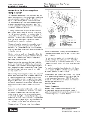
series will have six hex and two alien heads. For future 1. Shaft Seal 12. Center Section
2. Cap Screws
13. Drive Gear Assembly
reference, it would be helpful to scribe a line down the 3. Hex Screws 14. Driven Gear Assembly
outlet side of the pump. If you choose not to mark it, 4. Washers 15. Flow Control
(“H” Flow Divider Pump only)
5. Front Cover
the outlet port is usually the smallest. 6. V-Seal 16. Relief Valve
7. Dowel Pins (“H” Flow Divider Pump Only)
If the pump has a key-type shaft, remove the key and 8. Gasket 17. Back Cover
9. Heat Shield
18. Thrust Plate (H only)
hone down any burrs that may be on the shaft. This 10. Wear Plate 19. Key (Where Required)
is important as the next step will be to lift off the front 11. “0” Rings
cover, and any sharp edges could possibly damage the
front seal or bearing. into the center section, orienting the side with the bar
After the front cover is off, note the position of the little in line with the vent hole, ensuring that the bronze side
vent hole in the bronze wear plate, which should have faces the gears.
come off with the front cover. The parts underneath The rear cover is installed with the outlet side in line
also have a similar vent hole. with the vent hole. The outlet side will be marked or
Remove in order, the wear plate, the heat shield, the can be identified by the smaller, internal cavity. As when
gasket, and the V-seal. To facilitate this, make a small installing the center section, be careful not to pinch the
hook with a paper clip and lift the part high enough to O-ring seal.
slip a screwdriver under it and carefully pry up. Please The line that was originally scribed on the side should
note that the heat shield, in particular, is very brittle now be located at 180° on both the rear cover and cen-
and may crack if bent. ter section from that on the front cover.
After removing these four parts, reinstall the V-seal with Install the bolts and tighten down by hand. Then, torque
the lips down in the front cover so that the vent hole is to the proper setting, alternating from side to side. The
on the opposite side across from the reference mark. correct torque specifications are 190-210’’ lbs. for the ‘’
Use the screwdriver to seat it completely. Next, install D’’ and ‘’ H ‘’ series. Reverse or remove the rotation ar-
the gasket, heat shield, and wear plate; again with the row originally stamped on the
vent hole in line with that of the V-seal. The wear plate mounting flange.
should be almost flush with the surface of the front
cover. Testing Procedure
Remove the center section and note the notch cut on After the pump has been reinstalled, run for 2-3
the inside. This will be installed in line and next to the minutes before pressurizing. Try to apply pressure
vent hole in the wear plate. The dowel pins used to gradually for an additional five minutes, but do not pres-
locate the center section may be removed temporar- surize for longer than 5 seconds at a time.
ily to facilitate sliding the center section over the gear
assemblies. Be careful not to pinch the O-ring between
the front cover and center section. If it doesn’t want to
stay in place, it can be ‘’glued’’ using heavy grease.
If the pump is an “ H ‘’ series, install the thrust plate
29 Parker Hannifin Corporation
Gear Pump Division
Kings Mountain, North Carolina USA