
Page 24 - Parker - OSP-P Pneumatic Rodless Cylinders and Linear Guides
P. 24
Catalog 0980 OSP-P Pneumatic Rodless Cylinders and Linear Guides
Dimensions Standard Rodless Pneumatic Cylinders
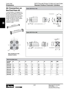
Air Connection on Series OSP-P16 to P32
the end-Face #5
In some situations it is necessary or
desirable to fit a special end cap with Air connection D �
the air connection on the end-face
instead of the standard end cap with
the air connection on the side. The
special end cap can also be rotated
4 x 90° to locate the cushion � �
adjustment screw as desired. ��
B Supplied in pairs. �� � Cushion adjustment screw �����
�
Series OSP-P40 to P80
1
4 2
Cushion adjustment screw Air connection D
5 3
Note: Position #2 is the
standard location.
Dimension table (mm)
Cylinder B C D e G H BX BW
Series
OSP-P16 14 30 M5 18 M3 9 1.8 10.8
OSP-P25 22 41 G1/8 27 M5 15 2.2 17.5
OSP-P32 25.5 52 G1/4 36 M6 15 2.5 20.5
OSP-P40 28 69 G1/4 54 M6 15 3 21
OSP-P50 33 87 G1/4 70 M6 15 – 27
OSP-P63 38 106 G3/8 78 M8 21 – 30
OSP-P80 47 132 G1/2 96 M10 25 – 37.5
B12 Parker Hannifin Corporation
Parker-Origa
ORIGA Glendale Heights, Illinois
www.parker.com/pneu/rodless