Page 20 - Parker - OSP-P Pneumatic Rodless Cylinders and Linear Guides
P. 20

Catalog 0980                                      OSP-P Pneumatic Rodless Cylinders and Linear Guides
            technical Data                                    Standard Rodless Pneumatic Cylinders

            Loads, Forces and                                                    ��
            Moments
                                                                                  ��
            Choice of cylinder is decided by:
            • Permissible loads, forces and
              moments
            • Performance of the pneumatic end
              cushions. The main factors here are         �  ��
              the mass to be cushioned and the
              piston speed at start of cushioning                                      ��   M = F ·l
              (unless external cushioning is used,          �                               Bending moments are
     B        e. g. hydraulic shock absorbers).                                             calculated from the
                                                                                            center of the linear
                                                                                            actuator
            The adjacent table shows the
            maximum values for light, shock-              theoretical   effective   max. Moments
            free operation, which must not be    Cylinder   Action   Action Force                  max.   Cushion
            exceeded even in dynamic operation.   Series   Force at      F        Mx   My    Mz   Load    Length
            Load and moment data are based       (mm Ø)    6 bar (N)  at 6 bar (N)  (Nm)  (Nm)  (Nm)  F (N)  (mm)
                                                                          A
            on speeds v ≤ 0.5 m/s.
            When working out the action force   OSP-P10      47          32      0.2    1   0.3    20      2.5 *
            required, it is essential to take into   OSP-P16  120        78      0.45   4   0.5    120     11
            account the friction forces generated   OSP-P25  295        250      1.5   15    3     300     17
            by the specific application or load.
                                                OSP-P32      483        420       3    30    5     450     20
                                                OSP-P40      754        640       6    60    8     750     27
                                                OSP-P50     1178        1000      10   115   15   1200     30
                                                OSP-P63     1870        1550      12   200   24   1650     32
                                                OSP-P80     3016        2600      24   360   48   2400     39
                                               * A rubber element (non-adjustable) is used for end cushioning.
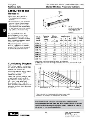
            Cushioning Diagram                   To deform the rubber element enough to reach the absolute end position would require a
                                                 Dp of 4 bar!
            Work out your expected moving mass
            and read off the maximum permissible    ���
            speed at start of cushioning.
            Alternatively, take your desired speed   �
            and expected mass and find the           �
                                                     �
            cylinder size required.                  �                      ���
            Please note that piston speed at start              ���  ���          ���
            of cushioning is typically ca. 50%       �                                   ���
            higher than the average speed, and   Max. permissible piston speed   ���  ���      ���
            that it is this higher speed which      ���
            determines the choice of cylinder. If   at start of cushioning  ���  ���
            these maximum permissible values are    ���
            exceeded, additional shock absorbers    ���
            must be used.                             ��� ������ ��� �  �  � �  ��       ���         ���� ��
                                                                                             Mass to be cushioned *


                                                * For cylinders with linear guides or brakes, please be sure to take
                                                  the mass of the carriage or the brake housing into account.


                                                If the permitted limit values are exceeded, either additional shock
                                                absorbers should be fitted in the area of the center of gravity or you can
                                                consult us about our special cushioning system  – we shall be happy to
                                                advise you on your specific application.


                                                             B8                        Parker Hannifin Corporation
                                                                                       Parker-Origa
                              ORIGA                                                    Glendale Heights, Illinois
                                                                                       www.parker.com/pneu/rodless
   15   16   17   18   19   20   21   22   23   24   25