Page 54 - Parker - OSP-P Pneumatic Rodless Cylinders and Linear Guides
P. 54

Catalog 0980                                      OSP-P Pneumatic Rodless Cylinders and Linear Guides
            Dimensions                                        Plain Bearing Guide SLIDeLINe

              Dimensions

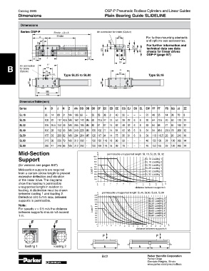
              Series OSP-P       Stroke + 2 x A           Air connection for brake (Option)
                                  Stroke
                                                                                       For further mounting elements
                                                                                       and options see accessories.
                                                                                       For further information and
                                                                                       technical data see data
                                                                                       sheets for linear drives
                                                                                       OSP-P (page B7)


     B       Air connection
             for brake
             (Option)
                                      type SL25 to SL80                                 type SL16


             Dimension table (mm)

             Series         A   B   J   M   Z   AA  BB  DB  DD  CF  eC  eD  ee   eG  eJ  eK  eL  eW  FF  Ft   FS  GG  JJ   ZZ
             SL 16         65   14   69  31  M4  106  88  –   30  55  36   8   40   30  –   –   –   22   48  55   14  36   70   8
             SL 25         100  22   117  40.5  M6  162  142  M5  60  72.5  47   12  53   39  22   6   6   30   64  73.5  20  50   120  12
             SL 32         125  25.5  152  49  M6  205  185  M5  80  91  67   14  62   48  32   6   6   33   84  88   21  64   160  12
             SL 40         150  28   152  55  M6  240  220  M5  100  102  77   14  64   50  58   6   6   34   94  98.5  21.5  78   200  12
             SL 50         175  33   200  62  M6  284  264  M5  120  117  94   14  75   56  81   6   6   39   110  118.5  26  90   240  16
             SL 63         215  38   256  79  M8  312  292  –   130  152  116  18  86   66  –   –   –   46   152  139   29  120  260  14
             SL 80         260  47   348  96  M8  312  292  –   130  169  116  18  99   79  –   –   –   46   152  165   29  120  260  14
            Mid-Section                                   �     permissable unsupported length: SL 16, SL 25, SL 32
            Support                                     ����                          SL 16 Loading 1
                                                        ���
                                                                                      SL 16 Loading 2
                                                        ���
            (for versions see pages B47)                ���                           SL 25 Loading 2
                                                        ���
            Mid-section supports are required          Load F  ���                    SL 25 Loading 1
                                                                                      SL 32 Loading 2
            from a certain stroke length to prevent     ���                           SL 32 Loading 1
                                                        ���
            exces sive deflection and vibration         ���
            of the line ar drive. The diagrams          ��� �
            show the maxi mum permissible                 ���  ���  ���  ���  ���  ���  ���  ���  ���  ���  ���  �
            unsupported length in relation to                                   distance between supports k
            loading. A distinc tion must be drawn
            between loading 1 and loading 2.            ���� �  permissable unsupported length: SL40, SL50, SL63, SL80
            Deflection of 0.5 mm max. between           ����                            SL40 Loading 2
            supports is permissible.                    ����                            SL40 Loading 1
                                                        ����                            SL50 Loading 2
            Note:                                       ����                            SL50 Loading 1
                                                        ����
            For speeds v > 0.5 m/s the distance        Load F  ����                     SL63 Loading 2
            between supports should not exceed          ����                            SL63 Loading 1
                                                                                        SL80 Loading 2
                                                        ����
            1 m.                                         ���                            SL80 Loading 1
                                                         ���
                   �              �                      ���
                                                         ���
                                                          �
                                                           ���  ���  ���  ���  ���  ���  ���  ���  ���  ���  ���  ���  ���  ���  ���  ���  �
                                                                                 distance between supports k
                                                             �                               �
                 loading 1       loading 2

                                                             B42                       Parker Hannifin Corporation
                                                                                       Parker-Origa
                              ORIGA                                                    Glendale Heights, Illinois
                                                                                       www.parker.com/pneu/rodless
   49   50   51   52   53   54   55   56   57   58   59