
Page 200 - Wagp_InterfaceElectronic_Volume4_2015_US.pdf
P. 200
857-819
3 JUMPFLEX Signal Conditioners
®
198 Millivolt Signal Conditioner from -100 mV … +100 mV and 0 mV … 1000 mV
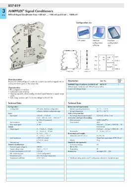
Configuration via:
DIP switch Interface Interface
configuration configuration
software app
<_________ 96 mm/3.76 in _________> IN+ 1 2 IN OUT 5 OUT+
U,I
mV
IN–
6 GND 1
N.C.
8 GND 2
_> N.C. 3 4 POWER 7 Us+
____________
_>
6 mm/0.23 in
<_________ 94 mm/3.68 in _________>
Short description: Pack.
The 857-819 Millivolt Signal Conditioner converts input millivolt signals into an Description Item No. Unit
analog standard signal on the output side. ®
JUMPFLEX Signal Conditioner, for DIN 35 rail 857-819 1
Millivolt Signal Conditioner with Millivolt Input as well as
Characteristics:
• PC configuration interface Current and Voltage Output
• Calibrated scale switching
• Clipping capability allows analog standard signal limitation to upper range
values
• Safe 3-way isolation with 2.5 kV test voltage to EN 61140
Technical Data Technical Data
Configuration: Environmental requirements:
Configuration DIP switch, interface configuration Ambient operating temperature -25 °C ... +70 °C
software, interface configuration app Storage temperature -40 °C ... +85 °C
Input: Safety and protection:
Input signal -100 mV ... +100 mV, Test voltage (input/output/supply) 2.5 kV AC, 50 Hz, 1 min
0 mV ... 200 mV, 0 mV ... 1000 mV * Connection and type of mounting:
®
(in 100 mV increments) Wire connection CAGE CLAMP S
Input resistance > 1MΩ Cross sections solid:
Max. input signal 31.2V 0.08 mm² ... 2.5 mm² / AWG 28 ... 14
Output: fine-stranded:
Output signal 0 ... 10 mA, 2 ... 10 mA, 0.34 mm² ... 2.5 mm² / AWG 22 ... 14
0 ... 20 mA, 4 ... 20 mA, Strip lengths 9 ... 10 mm / 0.37 in
0... 5 V, 1 ... 5 V, Dimensions and weight:
0 ... 10 V, 2 ... 10 V * Dimensions (mm) W x H x L 6 x 96 x 94
Load impedance ≤ 600 Ω (I output) Height from upper-edge of DIN 35 rail
≥ 2 kΩ (U output) Weight 50 g
Step response 50ms Standards and approvals:
General specifications: Conformity marking 1
24V DC r UL 508
Nominal supply voltage V S
Supply voltage range 16.8 V ... 31.2 V Shipbuilding g
Current consumption at 24 V DC ≤ 40 mA Accessories see pages 226 … 236
Min. measuring span 10 mV (configurable)
Transmission error ≤ 0.1 % of upper range value
Temperature coefficient ≤ 0.01 %/K ( * Additional setting options via PC configuration software or smartphone app)