
Page 202 - Wagp_InterfaceElectronic_Volume4_2015_US.pdf
P. 202
2857-533
3 JUMPFLEX Signal Conditioners
®
200 RTD Threshold Value Switch
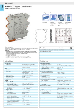
Configuration via:
DIP switch Interface Interface Configuration
configuration configuration display
software app
107 mm/4.21 in
110 mm/4.33 in 12,5 mm/0.49 in
Short description: Pack.
WAGO's RTD Threshold Value Switch for RTD sensors, potentiometers and resistors Description Item No. Unit
monitors and reports signals of up to two switching thresholds. ®
Features: JUMPFLEX Signal Conditioner, for DIN 35 rail 2857-533 1
• Both digital signal output and relay with make contact react to configured RTD Threshold Value Switch
measuring range limits (switching ON/OFF delay and threshold value switch
function configurable with up to two threshold values).
•Configurable RTD factor
• Adjustable software filter
• Input/Output response simulation via configuration display
• Safe 3-way isolation with 4 kV test voltage acc. to EN 61140
Technical Data Technical Data
Configuration: General specifications:
Configuration DIP switch, interface configuration Nominal supply voltage V S 24 VDC
software, interface configuration app, Supply voltage range 16.8 V … 31.2 V (-30 % … +30 %)
configuration display Current consumption at 24 VDC ≤ 40 mA + I DO
Input: Measurement error ± 1 K
Input signal RTD sensors, potentiometers and resistors Temperature coefficient ≤ 0.01 %/K
Sensor types Pt100, Pt200, Pt500, Pt1000, Environmental requirements:
Pt5000, Pt10000, Ambient operating temperature -40 °C … +70 °C
Pt10 … Pt20000 (expanded) Storage temperature -40 °C … +85 °C
Sensor connection 2-, 3-, and 4-wire, Difference Safety and protection:
Sensor supply current < 0.5 mA Test voltage
Temperature range -200 °C … +850 °C (input/output/supply) 4 kV AC, 50 Hz, 1 min.
Resistor input 0 … 100 kΩ Connection and type of mounting:
®
®
Output: Wire connection CAGE CLAMP S (picoMAX 5.0)
Output – Digital: Cross sections solid/fine-stranded:
Max. switching voltage Supply voltage applied -0.3 V 0.2 … 2.5 mm² / AWG 24 … 12
100 mA (no internal restriction) Strip length 9 … 10 mm / 0.35 … 0.39 in
Max. continuous current I DO
Number of switching tresholds 1 or 2 Dimensions and weight:
Configurable rise and 0 … 10 s (via DIP switch); Dimensions (mm) W x H x L 12.5 x 107 x 110
fall delay time 0 … 60 s (expanded) Height from upper-edge of DIN 35 rail
Output – Relay: Weight 86 g
Contact type 1 make contact (1 a) Standards and approvals:
Contact material AgNi (gold-plated) Conformity marking 1
Max. switching voltage 250 VAC Standards/Specifications DIN EN 50178:1997 (Basic isolation);
Max. continuous current 6 A (up to 60 °C), DIN EN 61010-1:2010;
(terminal blocks in a row) 3 A (60 °C … 70 °C) DIN EN 60664-1:2008; EN 61000-6-2;
Dielectric strength open contact EN 61000-6-4
(AC, 1 min) 1 kV rms Accessories: see pages 226 … 236
Pull-in/drop-out/bounce time typ. 8 ms / 4 ms / 8 ms
Number of switching tresholds 1 or 2
Configurable rise and 0 … 10 s (via DIP switch);
fall delay time 0 … 60 s (expanded)