Page 207 - Wagp_InterfaceElectronic_Volume4_2015_US.pdf
P. 207

3

                                                                                                                    205


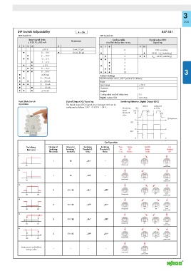
            DIP Switch Adjustability              ▯ = ON                                              857-531
             DIP Switch S1                                     DIP Switch S1
                   Input signal limits                                 Confi gurable           Digital output DO
                   ± 0.25 V; ± 0.5 mA        Hysteresis            rise/fall delay time in sec.  Signaling
             1  2  3  4              5                          6  7  8                 910
                            ±10 V             5 mV; 10 μA                     0                   DO not active
               ●           0 … 10 V  ●        10 mV, 20 μA      ●             1           ●     GND → U (switching)
                                                                                                     N
                  ●        2 … 10 V                               ●           2         ●  ●    U  → GND (switching)
                                                                                                 N
               ●  ●        0 … 5 V                              ●  ●          3
                    ●      1 … 5 V                                   ●        4
               ●    ●       ± 5 V                               ●    ●        5
                  ●  ●     0 … 15 V                               ●  ●        8
               ●  ●  ●     0 … 30 V                             ●  ●  ●       10                                    3
             ●             ± 20 mA                             Default Settings
             ●  ●         0 … 20 mA                            All DIP switches are in „OFF“ position for delivery.
             ●    ●       4 … 20 mA                            Input
             ●  ●  ●      0 … 10 mA                            Input range              ± 10 V
             ●      ●     2 … 10 mA                            Hysteresis               5 mV
             ●  ●   ●      ± 10 mA                             Output
                                                               Confi gurable rise/fall delay time  0 s
                                                               Digital output DO        not active
             Push/Slide Switch            Digital Output DO/Signaling       Switching Behavior, Digital Output (DO)
             Operation                    The digital output (DO) signals error messages and can be
                                          confi gured as follows: 24 V → 0 V/0 V → 24 V.   default  configured
                                                                             Measuring   %       to 75 %
                                                                             input/   100    !
                                                                             Measured   75           !
                                                                             value
                                                                                                         ! Hysteresis
                                                                                     0
                                                                                  DO
                                                                                     0
                                                                                  DO‘
                                                                                     0
                                                                                                        t
                                                                  Configuration
                  Switching    Number of   Values for   Switching   Switching   Press  Yellow  Red LED    No
                  Behavior      Switching   Switching T  Threshold 1,   Threshold 2,    for  LED  flashes  flashing
                                Thresholds  hresholds  Relay     Relay      1 sec.  flashes  briefly        LED
             1
                                  1         S1         „On“       –
                                                                             Param. mode  SP1           Leave
                 SP1
                                                                                                       param. mode
             2
                                  1         S1         „Off“      –
                                                                             Param. mode  SP1           Leave
                 SP1
                                                                                                       param. mode
             3
                                  2        S1 < S2     „On“       „Off“
                                                                             Param. mode   SP1   SP2    Leave
                 SP1    SP2
                                                                                                       param. mode
             4
                                  2        S1 < S2     „Off“      „On“
                 SP1    SP2                                                  Param. mode   SP1    SP2   Leave
                                                                                                       param. mode
             5
                                  2        S1 > S2     „On“       „Off“
                                                                             Param. mode  SP1    SP2    Leave
                 SP2    SP1
                                                                                                       param. mode
             6
                                  2        S1 > S2     „Off“      „On“
                                                                             Param. mode   SP1    SP2   Leave
                 SP2    SP1
                                                                                                       param. mode
              Leave param. mode without  –   –         –           –
                 storing a value
                                                                             Param. mode  Leave
                                                                                         param. mode
   202   203   204   205   206   207   208   209   210   211   212