
Page 214 - Wagp_InterfaceElectronic_Volume4_2015_US.pdf
P. 214
857-811
3 JUMPFLEX Signal Conditioners
®
212 Temperature Signal Conditioner for Thermocouples of Types J and K *
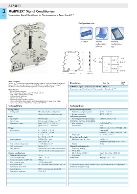
Configuration via:
DIP switch Interface Interface
configuration configuration
software app
<_________ 96 mm/3.76 in _________> TC+ 1 2 IN OUT 1 5 OUT+
TC–
6 GND 1
8 GND 2
_> 3 4 POWER 7 Us+
____________
_>
6 mm/0.23 in
<_________ 94 mm/3.68 in _________>
Short description: Pack.
The 857-811 Thermocouple Temperature Signal Conditioner is suitable for the connection of Description Item No. Unit
type J and K thermocouples. On the output side, the thermocouple temperature signal
®
conditioner converts the temperature signal into an analog standard signal. JUMPFLEX Signal Conditioner, for DIN 35 857-811 1
Characteristics: Temperature Signal Conditioner for Thermocouples of Types J and K *
• PC configuration interface
• For thermocouples of type J and K (E, R, N, S, T, B, C)
• Cold junction compensation (on/off)
• Calibrated scale switching
•Sensor's wire break
• Measuring range underflow/overflow
• Clipping capability allows analog standard signal limitation to upper range values
• Safe 3-way isolation with 2.5kV test voltage to EN 61140
Technical Data Technical Data
Configuration: Environmental requirements:
Configuration DIP switch, interface configuration Ambient operating temperature -25 °C ... +70 °C
software, interface configuration app Storage temperature -40 °C ... +85 °C
Input: Safety and protection:
Input signal Thermocouples Test voltage (input/output/supply) 2.5 kV AC, 50 Hz, 1 min
Sensor types Thermocouples of types J and K * Connection and type of mounting:
®
Temperature range Type J: -150 °C ... +1200 °C Wire connection CAGE CLAMP S
Type K: -150 °C ... +1350 °C Cross sections solid:
Output: 0.08 mm² ... 2.5 mm² / AWG 28 ... 14
Output signal 0 ... 10 mA, 2 ... 10 mA, fine-stranded:
0 ... 20 mA, 4 ... 20 mA, 0.34 mm² ... 2.5 mm² / AWG 22 ... 14
0... 5 V, 1 ... 5 V, Strip lengths 9 ... 10 mm / 0.37 in
0 ... 10 V, 2 ... 10 V * Dimensions and weight:
Load impedance ≤ 600 Ω (Out = mA) Dimensions (mm) W x H x L 6 x 96 x 94
≥ 2 kΩ (Out = V) Height from upper-edge of DIN 35 rail
Cold junction compensation on / off (default: on) * Weight 49.2 g
Cold junction error 3 K (typ. 2 K ) Standards and approvals:
Step response 60 ms without cold junction compensation/ Conformity marking 1
120 ms with cold junction compensation r UL 508
General specifications: r ANSI/ISA 12.12.01 Class I, Div. 2, Grp. ABCD, T4
24V DC Shipbuilding
Nominal supply voltage V S g
Supply voltage range 16.8 V ... 31.2 V Accessories see pages 226 … 236
Current consumption at 24 V DC ≤ 40 mA
Min. measuring span 100 K (configurable)
Transmission error ≤ 0.1 % at max. measuring span (Typ J, K) ( * Additional setting options as well as output signal inversion via PC configuration
Transmission error of set software or smartphone app)
measuring span (150 K / set measuring span [K]) %
Temperature coefficient ≤ 0.04 % /K