Page 219 - Wagp_InterfaceElectronic_Volume4_2015_US.pdf
P. 219

3

                                                                                                                    217


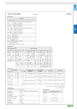
             DIP Switch Adjustability                ▯ = ON                                             857-820
             DIP Switch S1

                               Sensor Type
             1  2  3  4
                       KTY81-110, KTY81-120, KTY82-110, KTY82-120
             ●         KTY81-121, KTY82-121
               ●       KTY81-122, KTY82-122
             ●  ●      KTY81-150, KTY82-150
                  ●    KTY81-210, KTY81-220, KTY82-210, KTY82-220                                                   3
             ●    ●    KTY81-221, KTY82-221
               ●  ●    KTY81-222, KTY82-222
             ●  ●  ●   KTY81-250, KTY82-250
                     ● KTY83-110, KTY83-120,
             ●       ● KTY83-121
               ●     ● KTY83-122
             ●  ●    ● KTY83-150
                  ●  ● KTY83-151
             ●    ●  ● KTY84-130, KTY84-150
               ●  ●  ● KTY84-151
             ●  ●  ●  ● KTY16, KTY19, ST13, ST20
             DIP Switch S2
             Start Temperature                   End Temperature
             1  2  3  °C  4  5  6  7  8  °C  4  5  6  7  8  °C  4  5  6  7  8  °C
             ●       -55  ●              0   ●  ●    ●     100  ●    ●    ●   200
               ●     -50     ●          10        ●  ●     110     ●  ●   ●   210
             ●  ●    -40  ●  ●          20   ●    ●  ●     120  ●  ●  ●   ●   220
                  ●  -30       ●        30      ●  ●  ●    130          ●  ●  230
             ●    ●  -20  ●    ●        40   ●  ●  ●  ●    140  ●       ●  ●  240
               ●  ●  -10     ●  ●       50             ●   150     ●    ●  ●  250
             ●  ●  ●  0   ●  ●  ●       60   ●         ●   160  ●  ●    ●  ●  260
                                  ●     70      ●      ●   170       ●  ●  ●  270
                          ●       ●     80   ●  ●      ●   180  ●    ●  ●  ●  280
                             ●    ●     90        ●    ●   190     ●  ●  ●  ●  290
                                                                ●  ●  ●  ●  ●  300
             DIP Switch S1
                    Output Signal          Measuring Range   Measuring Range
             6  7  8                9 10     Underfl ow      Overfl ow       Wire Break     Short Circuit
                        0 … 20 mA        Lower limit of output range  Upper limit of output range  Upper limit of output range  Lower limit of output range
                                              -5 % ** 2     +2.5 %* 2        5 %* 2       -12.5 % ** 2
             ▯          4 … 20 mA
               ▯        0 … 10 mA                       Upper limit of output range  Upper limit of output range
                                    ▯    Lower limit of output range                   Lower limit of output range
             ▯  ▯       2 … 10 mA                            +2.5 %          5 %
                  ▯      0 … 10 V                         Upper limit of output   Upper limit of output range  Upper limit of output range
                                      ▯  Lower limit of output range
             ▯    ▯      2 … 10 V                             range          5 %            5 %
               ▯  ▯      0 … 5 V                          Upper limit of output
                                    ▯  ▯  Lower limit of output range  Lower limit of output range Lower limit of output range
             ▯  ▯  ▯     1 … 5 V                              range
                                                                       * but not when lower limit of output range = 0V or 0mA
                                                                                       2
             Default Setting                                                           *  acc. to NAMUR NE 43
             All DIP switches are in „OFF“ position for delivery.   DIP Switch S2
             Sensor type        KTY81-110, KTY81-120, KTY82-110, KTY82-120
                                                                             Digital Output DO Signaling
             Start temperature   0 °C                               910
             End temperature    100 °C
                                                                                  DO not active
             Output signal      0 … 20 mA
             Measuring range underfl ow  0 mA
                                                                       ●        DO  Us+ switching
             Measuring range overfl ow  20.5 mA
             Wire break         21 mA
                                                                    ●  ●        DO  GND switching
             Short circuit      0 mA
             Digital output     not active
   214   215   216   217   218   219   220   221   222   223   224