
Page 221 - Wagp_InterfaceElectronic_Volume4_2015_US.pdf
P. 221
3
219
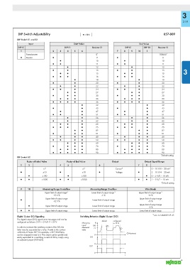
DIP Switch Adjustability ▯ = ON 857-809
DIP Switch S1 and S2
Input Start Value End Value
DIP S1 DIP S1 Resistor Ω DIP S1 DIP S2 Resistor Ω
1 2 3 4 5 6 7 8 9 10 1
Potentiometer 0 * 100000 *
▯ Resistor ● 0 ● 0
● 10 ● 10
● ● 11 ● ● 11
● 12 ● 12
● ● 13 ● ● 13 3
● ● 15 ● ● 15
● ● ● 16 ● ● ● 16
● 18 ● 18
● ● 20 ● ● 20
● ● 22 ● ● 22
● ● ● 24 ● ● ● 24
● ● 27 ● ● 27
● ● ● 30 ● ● ● 30
● ● ● 33 ● ● ● 33
● ● ● ● 36 ● ● ● ● 36
● 39 ● 39
● ● 43 ● ● 43
● ● 47 ● ● 47
● ● ● 51 ● ● ● 51
● ● 56 ● ● 56
● ● ● 62 ● ● ● 62
● ● ● 68 ● ● ● 68
● ● ● ● 75 ● ● ● ● 75
● ● 82 ● ● 82
● ● ● 91 ● ● ● 91
● ● ● 40 ● ● ● 40
● ● ● ● 50 ● ● ● ● 50
● ● ● 60 ● ● ● 60
● ● ● ● 70 ● ● ● ● 70
● ● ● ● 80 ● ● ● ● 80
● ● ● ● ● 90 ● ● ● ● ● 90
* Default setting
DIP Switch S2
Factor of Initial Value Factor of End Value Output Output Signal Range
2 3 4 5 6 7 8
x1 * x1 * Current* 0 – 10 V/0 – 20 mA *
● x10 ● x10 ● Voltage ● 2 – 10 V/4 – 20 mA
● x100 ● x100 ● 0 – 5 V/0 – 10 mA
● ● x1000 ● ● x1000 ● ● 1 – 5 V/2 – 10 mA
*
Default setting
9 10 Measuring Range Underfl ow Measuring Range Overfl ow Wire Break
Upper limit of output range *1 Lower limit of output range *1 Upper limit of output range *1
+2.5 % -5 % +5 %
Upper limit of output range Upper limit of output range
● Lower limit of output range
+2.5 % +5 %
Upper limit of output range
● Upper limit of output range Lower limit of output range
+5 %
● ● Upper limit of output range Lower limit of output range Lower limit of output range
*1 acc. to NAMUR NE 45
Digital Output DO/Signaling Switching Behavior, Digital Output (DO)
The digital output (DO) signals error messages and can be
confi gured as follows: 24 V → 0 V/0 V → 24 V. default configured
Measuring % to 75 %
input/ 100 !
In order to increase the switching current of the DO, the Measured 75 !
latter may be expanded by a relay. Thanks to the contour value
uniformity of Series 857, for example, a 857-304 Relay ! Hysteresis
can be snapped in next to it. This output can be quickly and 0
easily expanded to a switching current of 6A by simply using DO
an adjacent jumper (859-402).
0
DO‘
0
t