Page 245 - Wagp_InterfaceElectronic_Volume4_2015_US.pdf
P. 245

4

                                                                                                                    243


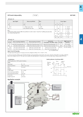
            DIP Switch Adjustability              ▯ = ON                                              857-550


             DIP Switch  S1
                    Input Signal        Measuring Method   Filter                       Output Signal

             1                     2                     3                      4   5   6
               5 A                   Mean square value      off                                 0 ... 20 mA
             ● 1 A                 ● Arithmetic mean value  ● active                ●          4 ... 20 mA
                                                                                ●              0 ... 10 V
            Filter
                                                                                ●   ●          2 ... 10 V
            The fi lter function allows a low-pass fi lter to be switched on in order to mask or “smooth out” oscillating measured values
            (e.g., during trailing edge fl ows).                                         ●      0 ... 10 mA
                                                                                    ●   ●      2 ... 10 mA
                                                                                ●       ●       0 ... 5 V
                                                                                ●   ●   ●       1 ... 5 V
                                                                                                                    4
             DIP Switch  S1
                                                                      Overcurrent            Digit Output DO
                    Measuring Range Underfl ow  Measuring Range Overfl ow
             7  8                                               (Input Signal - End Value + 20%)  910  Signaling
                   Lower limit of measuring range -5 % *  Upper limit of measuring range +2.5 % *  Upper limit of measuring range +5 %  *  DO not active
             ●      Lower limit of measuring range  Upper limit of measuring range +2.5 %  Upper limit of measuring range +5 %  ●  DO  Us+ switching
               ●    Lower limit of measuring range  Upper limit of measuring range  Lower limit of measuring range  ●  ●  DO GND switching
             ●  ●   Lower limit of measuring range  Upper limit of measuring range  Upper limit of measuring range
                                                                       * acc. to NAMUR NE 43
            Digital Output DO/Signaling
            The digital output (DO) signals error messages and can be confi gured as follows: 24 V → 0 V/0 V → 24 V.
            In order to increase the switching current of the DO, the latter may be expanded by a relay. Thanks to the contour uniformity of Series 857, for example, a 857-304
            Relay can be snapped in next to it. This output can be quickly and easily expanded to a switching current of 6A by simply using an adjacent jumper (859-402).

             Default Setting                                        Switching Behavior, Digital Output (DO)
             All DIP switches are in “OFF“ position for delivery.
                                                                                 default  configured
             Input                                                   Measuring   %      to 75 %
                                                                     input/   100   !
             Input Signal       0 ... 5 A                            Measured   75           !
                                                                     value
             Measuring Method   Mean square value
                                                                                                 ! Hysteresis
             Filter             not active                                   0
             Output                                                       DO
             Output Signal      0 ... 20 mA
                                                                             0
             Measuring Range Underfl ow  0 mA                              DO‘
             Measuring Range Overfl ow  20.5 mA
             Overcurrent        21 mA                                        0
                                                                                                t
             Digital Output DO  not active
            Application example:


              Current                                                         PLC/
              Transformer                                            4 ... 20 mA  LED indication
              250 A/ 1 A


                                                                             e.g. 787-1002
                                                                             16.8 ... 31.2 V
                        DO/
                        LED indication
                        24 V/500 mA
                                                                                 230 VAC


                L1
   240   241   242   243   244   245   246   247   248   249   250