Page 246 - Wagp_InterfaceElectronic_Volume4_2015_US.pdf
P. 246

857-552

   4    JUMPFLEX  Signal Conditioners
                     ®
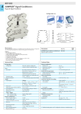
  244   Rogowski Signal Conditioner


                                                                     Configuration via:


                                                                      DIP switch    Interface    Interface
                                                                                    configuration   configuration
                                                                                    software     app

                                                                         <_________ 96 mm/3.76 in _________>  (GND 1)   1  IN  OUT  5 OUT+
                                                                                       RC1+

                                                                                     GND 1
                                                                                                       6 GND 2
                                                                                           2
                                                                                       RC2+
                                                                                        DO
                                                                                           4 DO
                                                                                                       8 GND 3
                                                                                 _>  (GND 1)   3   POWER 7 Us+
                                                                     ____________   (GND 3)
                                                                             _>
                                                                            6 mm/0.23 in
                                                       <_________ 94 mm/3.68 in _________>
        Short description:                                                                                Pack.
        The Rogowski Signal Conditioner records RMS values from alternating currents via a Rogowski   Description  Item No.
        coil, converting the input signal into a standard analog signal on the output side.               Unit
                                                                    ®
                                                              JUMPFLEX  Signal Conditioner, for DIN 35 rail  857-552  1
        Features:
        • PC configuration interface                          Rogowski Signal Conditioner
        • Supports different types of Rogowski coils
        • Digital switching output (configurable switching thresholds)
        • True RMS measurement (TRMS)
        • Configurable output signal
        • Configuration via DIP switch
        • Safe 3-way isolation with 2.5 kV test voltage acc. to EN 61140
        • No current bar interruption during installation
        • Measuring range overflow indication
        Technical Data                                        Technical Data
        Configuration:                                        General specifications:
          Configuration           DIP switch, interface configuration   Linearity error   ≤ 0,1 %
                                  software, interface configuration app  Temperature coefficient  ≤ 0.01 %/K
        Input:                                                  Measurement error      < 1 %
          Input signal            RC1 500 A: Sensitivity 10.05 mV *  Line length       < 3 m (to the Rogowski coil)
                                  RC2A 2000 A: Sensitivity 40.2 mV *  Environmental requirements:
                                  RC2B: Sensitivity 100 mV *    Ambient operating temperature  -25 °C ... +70 °C (at rated current)
                                  50/60 Hz sinusoidal and distorted   Storage temperature  -40 °C ... +85 °C
                                  sinusoidal signals (e.g. leading edge and   Safety and protection:
          Frequency range         16 Hz ... 1000 Hz             Test voltage
          Response threshold      < 1 % (of measuring range nominal value)  (input/output/supply)  2.5 kV AC, 50 Hz, 1 min.
        Output:                                               Connection and type of mounting:
                                                                                                ®
          Output signal           Voltage:                      Wire connection        CAGE CLAMP  S
                                  0 ... 5 V, 1 ... 5 V, 0 ... 10 V, 2 ... 10 V *  Cross sections  solid: 0.08 mm² ... 2.5 mm² / AWG 28 ...
                                  Current: 0 ... 10 mA, 2 ... 10 mA,                   14
                                  0 ... 20 mA, 4 ... 20 mA *                           fine-stranded: 0.34 mm² ... 2.5 mm² /
          Overcurrent             0 % or +5 % (e. g. 10.5 V/21 mA)                     AWG 22 ... 14
          Measuring range overflow/underflow  0 % or +2.5 %     Strip lengths          9 ... 10 mm / 0.37 in
          Load impedance          Current ≤ 600 Ω, Voltage ≥ 1000 Ω  Dimensions and weight:
          Measuring procedure     True RMS (TRMS)               Dimensions (mm) W x H x L  6 x 96 x 94
          Filter (T 10-90 )       600 ms (50 Hz)                                       Height from upper-edge of DIN 35 rail
          Output - Digital                                      Weight                 36.2 g
            Max. switching voltage  Supply voltage applied    Standards and approvals:
            Max. continuous current  500 mA                     Conformity marking     1
        General specifications:                                 Shipbuilding           g
                                  24 VDC                      Accessories              see pages 226 … 236
          Nominal supply voltage V S
          Supply voltage range    16.8 V ... 31.2 V                                    Rogowski Coils see Section 4
          Current consumption at 24 V DC  ≤ 40 mA
          Resolution              500 A measuring range: 250 mA,
                                  2000 A measuring range: 1000 mA
          Measuring procedure     True RMS (TRMS)
          Response time           1.5 ms + signal cycle duration
          Max. operating frequency  < 2 kHz                   ( * Additional setting options via PC configuration software or smartphone app)
          Response time (T 10-90 )  max. 60 ms
   241   242   243   244   245   246   247   248   249   250   251