
Page 251 - Wagp_InterfaceElectronic_Volume4_2015_US.pdf
P. 251
4
249
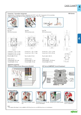
Connection / Connection Assignment 855 Series
Implementation of the primary winding is designated with “K-P1” and “L-P2.” Connections for the secondary
winding are designated with the corresponding lower case letters “ k-S1” and “I-S2.”
Dimensions:
Item No. Item No. Item No.
855-3xx/xxxx-xxxx 855-4xx/xxxx-xxxx 855-5xx/xxxx-xxxx
4
Current bar 1: 30 x 10 mm Current bar 1: 40 x 10 mm Current bar 1: 50 x 12 mm
Current bar 2: 25 x 12 mm Current bar 2: 30 x 15 mm Current bar 2: 40 x 30 mm
Current bar 3: 20 x 20 mm
Round cable: 26 mm Round cable: 32 mm Round cable: 44 mm
Width: 60 mm Width: 70 mm Width: 85 mm
Overall height: 80.5 mm Overall height: 91 mm Overall height: 105.25 mm
Overall depth: 52 mm Overall depth: 52 mm Overall depth: 52 mm
Application examples:
®
750 Series (3-Phase Power Measurement Module) 857 Series (JUMPFLEX Current Transducer)
Current
transformer
250 A/1 A PLC/
LED indication
2007-7783
Connector assembly L1
for current DO/ e.g. 787-1002
LED indication
transformer 24 V/500 mA 16.8 ... 31.2 V
230 VAC
Mounting Options
Mounting on round cable Mounting on copper current Mounting on carrier rail with Mounting on mounting plate Quick-mount installa-
bar carrier rail adapter tion for conductors
Note:
* The carrier rail adapter is only suitable for 855-3xx/xxxx-xxxx and 855-4xx/xxxx-xxxx transformers.