
Page 58 - Wagp_InterfaceElectronic_Volume4_2015_US.pdf
P. 58
1 Sockets with Industrial Relay
56
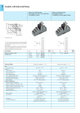
Socket with industrial relay Socket with industrial relay
Coil voltage: 24 V, 48 V, 110 V, 220 v DC Coil voltage: 24 V DC
4 changeover contacts 4 changeover contacts (gold contacts)
Switching current (A) 2 contacts in serie
10 5 DC resistive load 1 contact
3 contacts in serie
4 contacts in serie
1
0.5
0.3
0.2 DC inductive load,
L/R = 40 ms
0.1
10 20 30 50 100 200 300
Switching voltage (V)
DC load limit curve 14 14
11 11
12 12
24 24
A1 A1
* In order to prevent the gold layer from being damaged, + 21 + 21
22 22
30 VDC switching voltages and 50 mA currents shall not 34 34
be exceeded. 31 31
A2 A2
Higher switching power leads to evaporation of the gold - 32 - 32
44 44
layer. The resulting deposits in the enclosure may cause 41 41
sparkovers between the coil and the contact. 42 42
Description Item No. Pack. Item No. Pack.
V N
I N
Unit V N I N Unit
Socket with industrial relay, 24 VDC 36.9 mA 858-304 1 24 VDC 36.9 mA 858-314 1
for DIN 35 rail 48 VDC 18.5 mA 858-305 1
110 VDC 10 mA 858-307 1
220 VDC 4.1 mA 858-308 1
Technical Data Accessories see pages 61 … 65 Accessories see pages 61 … 65
Coil:
Input voltage range V N -20 % ... +10 % V N -20 % ... +10 %
Contacts:
Contact material AgCe AgCe + Au
Max. continuous current 5 A 5 A *
Max. make current 15 A (4 s) 15 A (4 s)
Max. switching voltage 250 VAC 250 VAC *
Max. switching power (resistive) 1250 VA AC, DC see load limit curve 1250 VA AC, DC see load limit curve *
Recommended minimum load 100 mA / 12 V AC/DC 1 mA / 5 VDC / 50 mW
Pull-in/drop-out/bounce time typ. 25ms / 25ms / 4 ms 25ms / 25ms / 4 ms
6
6
Mechanical life 20 x 10 switching operations 20 x 10 switching operations
General specifications:
Nominal voltage to EN 60664-1 250 V / 2.5 kV / 2 250 V / 2.5 kV / 2
Dielectric strength, contact-coil (AC, 1 min) 1.5 kV rms 1.5 kV rms
Dielectric strength open contact (AC, 1 min) 1 kV rms 1 kV rms
Dielectric strength contact-contact (AC, 1 min) 1.5 kV eff 1.5 kV eff
-25 °C ... +70 °C -25 °C ... +70 °C
Ambient operating temperature at V N
Storage temperature -40 °C ... +80 °C -40 °C ... +80 °C
Dimensions (mm) W x H x L 31 x 73 x 97 31 x 73 x 97
Height from upper-edge of DIN 35 rail Height from upper-edge of DIN 35 rail
®
®
Wire connection CAGE CLAMP S CAGE CLAMP S
Cross sections 2 x 0.34 mm² ... 2 x 1.5 mm² / 2 x 0.34 mm² ... 2 x 1.5 mm² /
1 x 2.5 mm²/ 1 x 2.5 mm²/
AWG 22 ... 16 AWG 22 ... 16
Strip length 9 … 10 mm / 0.35 … 0.39 in 9 … 10 mm / 0.35 … 0.39 in
Standards/specifications EN 61810-1; EN 60664-1; EN 61810-1; EN 60664-1;
(858-304: GL; UL 508, max. 50 °C) GL; UL 508 (max. 50 °C)