
Page 4 - Parker - Assembly/Installation
P. 4
4300 Catalog Assembly / Installation
Port End Assembly
Counterbores and taps used to machine the various parallel 6. To align the tube end of the
thread ports can be found in section R. fitting to accept incoming tube
or hose assembly, unscrew the
For assembly purposes, there are two main categories of fitting by the required amount, but
parallel port ends: adjustable and non-adjustable. Adjustable not more than one full turn.
port ends are commonly found on shaped fittings to allow for
proper orientation of the fitting. Besides the elastomeric seal,
adjustable port ends are assembled with a locknut and a back- 7. Using two wrenches, hold
up washer as shown in Fig. S6. Non-adjustable port ends are fitting in desired position and Step 6
found on straight fittings. tighten locknut to the proper torque
value from the appropriate table
located on pages S5 - S6.
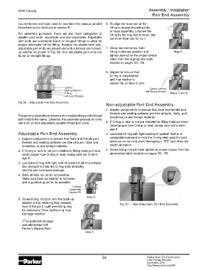
8. Inspect to ensure that
O-ring is not pinched
and that washer is
seated flat on face of port.
Locknut Tighten Locknut
Back-up Washer with Torque Wrench
O-Ring Steps 7 and 8
Left-hand Threads
Fig.S6 – Adjustable Port End Assembly
Non-adjustable Port End Assembly
1. Inspect components to ensure that male and female port
threads and sealing surfaces are free of burrs, nicks, and
The general assembly procedure for all adjustable parallel thread scratches, or any foreign material.
port ends is the same. Likewise, the assembly procedure is the
same for all non-adjustable parallel thread port ends. 2. If O-ring or seal is not pre-installed to fitting male port end,
install proper size O-ring or seal, taking care not to dam-
age it.
Adjustable Port End Assembly 3. Lubricate O-ring with light coating of system fluid or a
1. Inspect components to ensure that male and female port compatible lubricant to help the O-ring slide past the port
threads and sealing surfaces are free of burrs, nicks and entrance corner and avoid damaging it. “ED” seal does not
scratches, or any foreign material. need lubrication.
2. If O-ring or seal is not pre-installed to fitting male port end, 4. Screw fitting into port and tighten to proper torque from the
install proper size O-ring or seal, taking care not to dam- appropriate table located on pages S5 - S6.
age it.
3. Lubricate O-ring with light coat of system fluid or a compat-
ible lubricant to help the O-ring slide smoothly
into the port and avoid damage.
4. Back off lock nut as far as possible.
Make sure back-up washer is not loose
and is pushed up as far as possible.
Locknut
Completely
Backed-Off
Step 4
5. Screw fitting into port until the back-up
washer or the retaining ring contacts Fig. S7 — Non-Adjustable Port End Assembly
face of the port. Light wrenching may
be necessary. Over tightening may
damage washer.
(This potential damage
was eliminated with
Parker’s Robust Port)
Step 5
S4 Parker Hannifin Corporation
Tube Fittings Division
Columbus, Ohio
http://www.parker.com/tfd