
Page 257 - Parker - Parker Pneumatic
P. 257
PDE2600PNUK
Parker Pneumatic Large Air Motors - P1V-A
P1V-A Air Motor - Planetary Gear
NOTE! All technical data are based on a working
pressure of 6 bar and with oil.
Speed tolerance accuracy is -+10%.
B: Reversible motor with planetary gear, flange mounting, free installation position
Max Max Nominal Nominal Min Max Air Connection Min pipe Weight Order code
power speed* speed Torque start permanent consumption ID inlet/
torque torque** at max power outlet
kW rpm rpm Nm Nm Nm l/s mm Kg
Series P1V-A160
1,600 1200 900 16 24 40 32 G1/2 15 8,3 P1V-A160B0120
1,600 600 450 32 48 35 32 G1/2 15 8,3 P1V-A160B0060
1,600 190 180 77 115 100 32 G1/2 15 15,4 P1V-A160B0019
Series P1V-A260
2,600 1200 700 34 51 40 60 G3/4 19 12,0 P1V-A260B0120
2,600 600 350 67 100 40 60 G3/4 19 12,0 P1V-A260B0060
2,600 190 140 160 240 40 60 G3/4 19 13,0 P1V-A260B0019
Series P1V-A360
3,600 960 600 55 82 100 97 G1 25 25,5 P1V-A360B0096
3,600 480 300 110 165 100 97 G1 25 25,5 P1V-A360B0048
* maximum admissible speed (idling)
** Max gear box torque for a permanent load
Permitted shaft loadings
The following calculations should be used to determine the
loading on the output shaft bearing, if a service life of -F ax +F ax
10,000,000 revolutions of the output shaft is to be obtained
with 90% probability.
F = max 0,24 × F rad r +F rad
ax
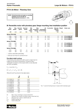
M = ± F × r ± F × (X + K)
ax
rad
Where M and K are found in the table below
M K
Nm N
P1V-A160B120 2651 0,031 -F rad
P1V-A160B060 2651 0,031
P1V-A160B019 7385 0,040 X
P1V-A160B010 7385 0,040
P1V-A260B120 2651 0,031 Fig 2: Load and braking torque on output shaft of planetary gear
P1V-A260B060 2651 0,031
P1V-A260B019 7385 0,040
P1V-A360B096 7385 0,040
P1V-A360B048 7385 0,040
M Max. torque loading on output shaft (Nm)
r Distance from centre of output shaft to axial load (m)
X Distance from collar to radial load (m)
F Radial loading (N)
rad
F Axial loading (N)
ax
Parker Hannifin Corporation
Pneumatic Division - Europe
257