
Page 263 - Parker - Parker Pneumatic
P. 263
PDE2600PNUK
Parker Pneumatic Large Air Motors - P1V-A
P1V-A Air Motor - Worm Gear
NOTE! All technical data are based on a working
pressure of 6 bar and with oil.
Speed tolerance accuracy is -+10%.
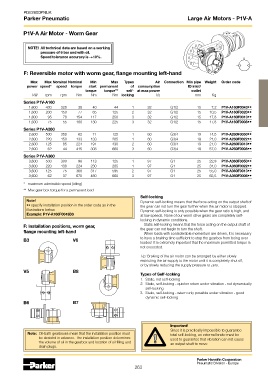
F: Reversible motor with worm gear, flange mounting left-hand
Max Max Nominal Nominal Min Max Types Air Connection Min pipe Weight Order code
power speed* speed torque start permanent of consumption ID inlet/
torque torque** self- at max power outlet
kW rpm rpm Nm Nm Nm locking l/s mm Kg
Series P1V-A160
1,600 430 320 38 40 44 1 32 G1/2 15 7,2 P1V-A160F0043••
1,600 200 150 77 65 125 2 32 G1/2 15 10,5 P1V-A160F0020••
1,600 95 70 154 117 250 3 32 G1/2 15 17,8 P1V-A160F0010••
1,600 75 55 180 130 225 3 32 G1/2 15 17,8 P1V-A160F0008••
Series P1V-A260
2,600 500 350 62 71 125 1 60 G3/4 19 14,5 P1V-A260F0050••
2,600 220 150 133 133 285 1 60 G3/4 19 21,0 P1V-A260F0022••
2,600 125 85 224 191 430 2 60 G3/4 19 21,0 P1V-A260F0013••
2,600 62 44 415 308 660 3 60 G3/4 19 57,0 P1V-A260F0008••
Series P1V-A360
3,600 500 300 98 113 125 1 97 G1 25 22,9 P1V-A360F0050••
3,600 220 130 224 230 285 1 97 G1 25 31,0 P1V-A360F0022••
3,600 125 75 368 317 595 2 97 G1 25 55,0 P1V-A360F0013••
3,600 62 37 670 480 660 3 97 G1 25 65,5 P1V-A360F0006••
* maximum admissible speed (idling)
** Max gear box torque for a permanent load
Self-locking
Note! Dynamic self-locking means that the force acting on the output shaft of
•• specify installation position in the order code as in the the gear can not turn the gear further when the air motor is stopped.
illustrations below. Dynamic self-locking is only possible when the gear ratio is high, and
Example: P1V-A160F0043B3 at low speeds. None of our worm drive gears are completely self-
locking in dynamic conditions.
F: Installation positions, worm gear, Static self-locking means that the force acting on the output shaft of
the gear can not begin to turn the shaft.
flange mounting left-hand When loads with considerable momentum are driven, it is necessary
B3 V6 to have a braking time sufficient to stop the gearbox from being over-
loaded. It is extremely important that the maximum permitted torque is
not exceeded.
Tip: Braking of the air motor can be arranged by either slowly
restricting the air supply to the motor until it is completely shut off,
or by slowly reducing the supply pressure to zero.
V5 B8
Types of Self-locking
1. Static, not self-locking
2. Static, self-locking - quicker return under vibration - not dynamically
self-locking
3. Static, self-locking - return only possible under vibration - good
dynamic self-locking
B6 B7
Important!
Since it is practically impossible to guarantee
Note: Oil-bath gearboxes mean that the installation position must total self-locking, an external brake must be
be decided in advance. The installation position determines used to guarantee that vibration can not cause
the volume of oil in the gearbox and location of oil filling and an output shaft to move.
drain plugs.
Parker Hannifin Corporation
Pneumatic Division - Europe
263