
Page 17 - Parker - Isysnet serial bus system selection guide
P. 17
Isysnet 15
Step 5 – Placing Isysnet Modules
Determining Mounting Requirements
For a Rockwell controller to control Isysnet, the I/O must be:
The producer/consumer model multicasts messages. This
means that multiple nodes can consume the same data at the • On the same network as the controller or
same time from a single device. Where you place I/O modules in • On a ControlNet network that is local to that controller or
the control system determines how the modules exchange data.
• On an EtherNet/IP network that is local to that controller
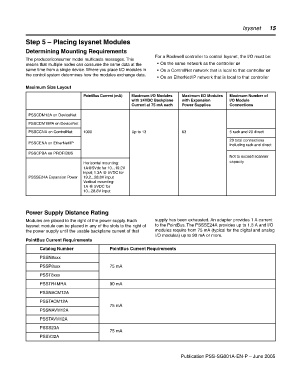
Maximum Size Layout
PointBus Current (mA) Maximum I/O Modules Maximum I/O Modules Maximum Number of
with 24VDC Backplane with Expansion I/O Module
Current at 75 mA each Power Supplies Connections
PSSCDM12A on DeviceNet
PSSCDM18PA on DeviceNet
PSSCCNA on ControlNet 1000 Up to 13 63 5 rack and 20 direct
20 total connections
PSSCENA on EtherNet/IP
including rack and direct
PSSCPBA on PROFIBUS
Not to exceed scanner
Horizontal mounting: capacity
1A@5Vdc for 10...19.2V
input; 1.3A @ 5VDC for
PSSSE24A Expansion Power 19.2...28.8V input
Vertical mounting:
1A @ 5VDC for
10...28.8V input
Power Supply Distance Rating
Modules are placed to the right of the power supply. Each supply has been exhausted. An adapter provides 1 A current
Isysnet module can be placed in any of the slots to the right of to the PointBus. The PSSSE24A provides up to 1.3 A and I/O
the power supply until the usable backplane current of that modules require from 75 mA (typical for the digital and analog
I/O modules) up to 90 mA or more.
PointBus Current Requirements
Catalog Number PointBus Current Requirements
PSSN8xxx
PSSP8xxx 75 mA
PSST8xxx
PSSTR4MRA 90 mA
PSSNACM12A
PSSTACM12A
75 mA
PSSNAVM12A
PSSTAVM12A
PSSS23A
75 mA
PSSV32A
Publication PSS-SG001A-EN-P – June 2005