
Page 8 - Parker - Isysnet serial bus system selection guide
P. 8
6 Isysnet
Digital I/O Modules Digital DC Input Modules
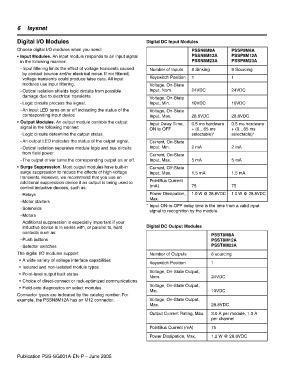
Choose digital I/O modules when you need: PSSN8M8A PSSP8M8A
• Input Modules. An input module responds to an input signal PSSN8M12A PSSP8M12A
in the following manner: PSSN8M23A PSSP8M23A
- Input filtering limits the effect of voltage transients caused Number of Inputs 8 Sinking 8 Sourcing
by contact bounce and/or electrical noise. If not filtered,
voltage transients could produce false data. All input Keyswitch Position 1 1
modules use input filtering. Voltage, On-State
- Optical isolation shields logic circuits from possible Input, Nom. 24VDC 24VDC
damage due to electrical transients.
Voltage, On-State
- Logic circuits process the signal. Input, Min. 10VDC 10VDC
- An input LED turns on or off indicating the status of the Voltage, On-State
corresponding input device. Input, Max. 28.8VDC 28.8VDC
• Output Modules. An output module controls the output
Input Delay Time, 0.5 ms hardware 0.5 ms hardware
signal in the following manner:
ON to OFF + (0…65 ms + (0…65 ms
- Logic circuits determine the output status. selectable)* selectable)*
- An output LED indicates the status of the output signal. Current, On-State
- Optical isolation separates module logic and bus circuits Input, Min. 2 mA 2 mA
from field power.
Current, On-State
- The output driver turns the corresponding output on or off. Input, Max. 5 mA 5 mA
• Surge Suppression. Most output modules have built-in Current, Off-State
surge suppression to reduce the effects of high-voltage Input, Max. 1.5 mA 1.5 mA
transients. However, we recommend that you use an
additional suppression device if an output is being used to PointBus Current
(mA) 75 75
control inductive devices, such as:
- Relays Power Dissipation, 1.0 W @ 28.8VDC 1.0 W @ 28.8VDC
Max.
- Motor starters
* Input ON-to-OFF delay time is the time from a valid input
- Solenoids
signal to recognition by the module.
- Motors
Additional suppression is especially important if your
inductive device is in series with, or parallel to, hard Digital DC Output Modules
contacts such as:
PSST8M8A
- Push buttons PSST8M12A
- Selector switches PSST8M23A
The digital I/O modules support: Number of Outputs 8 sourcing
• A wide variety of voltage interface capabilities
Keyswitch Position 1
• Isolated and non-isolated module types
Voltage, On-State Output,
• Point-level output fault states
Nom. 24VDC
• Choice of direct-connect or rack-optimized communications
Voltage, On-State Output,
• Field-side diagnostics on select modules
Min. 10VDC
Connector types are indicated by the catalog number. For
example, the PSSN8M12A has an M12 connector. Voltage, On-State Output,
Max. 28.8VDC
Output Current Rating, Max. 3.0 A per module, 1.0 A
per channel
PointBus Current (mA) 75
Power Dissipation, Max. 1.2 W @ 28.8VDC
Publication PSS-SG001A-EN-P – June 2005