
Page 75 - Parker- Parker global air preparation system
P. 75
Catalog 0750-3 US P33T Series
Global Air Preparation System Redundant Safety Exhaust Valves
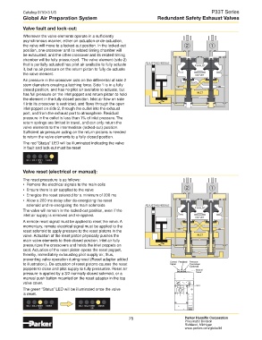
Valve fault and lock-out:
Whenever the valve elements operate in a sufficiently
asynchronous manner, either on actuation or de-actuation,
the valve will move to a locked-out position. In the locked-out 2 1
position, one crossover and its related timing chamber will
be exhausted, and the other crossover and its related timing
chamber will be fully pressurized. The valve element (side 2)
that is partially actuated has pilot air available to fully actuate ADJUSTING NEEDLE EXHAUST
it, but no air pressure on the return piston to fully de-actuate
the valve element. OUTLET
Air pressure in the crossover acts on the differential of side 2
stem diameters creating a latching force. Side 1 is in a fully
closed position, and has no pilot air available to actuate, but
has full pressure on the inlet poppet and return piston to hold INLET
the element in the fully closed position. Inlet air flow on side
1 into its crossover is restricted, and flows through the open
inlet poppet on side 2, through the outlet into the exhaust
port, and from the exhaust port to atmosphere. Residual
pressure in the outlet is less than 1% of inlet pressure. The
return springs are limited in travel, and can only return the
valve elements to the intermediate (locked-out) position.
Sufficient air pressure acting on the return pistons is needed
to return the valve elements to a fully closed position.
The red “Status” LED will be illuminated indicating the valve
in fault and lock-out must be reset
SOL.1 SOL.2 RESET STATUS
SOL
Valve reset (electrical or manual):
The reset procedure is as follows:
• Remove the electrical signals to the main coils
• Ensure there is air supplied to the valve 2 1
• Energize the reset solenoid for a minimum of 200 ms
• Allow a 200 ms delay after de-energizing the reset
solenoid and re-energizing the main solenoids ADJUSTING NEEDLE
EXHAUST
The valve will remain in the locked-out position, even if the
inlet air supply is removed and re-applied.
OUTLET
A remote reset signal must be applied to reset the valve. A
momentary, remote electrical signal must be applied to the
reset solenoid to apply pressure to the reset pistons in the
valve. Actuation of the reset piston physically pushes the INLET
main valve elements to their closed position. Inlet air fully
pressurizes the crossovers and holds the inlet poppets on
seat. Actuation of the reset piston opens the reset poppet,
thereby, immediately exhausting pilot supply air, thus,
preventing valve operation during reset (Reset adapter added
to illustration.). De-actuation of reset pistons causes the reset Control Feedback Pressure
Transducer
Signal
poppets to close and pilot supply to fully pressurize. Reset air (Optional)
Manual
pressure is applied by a 3/2 normally closed solenoid, or a Reset
manual push button mounted on the reset adapter in the top
valve cover.
Inlet
The green “Status” LED will be illuminated once the valve
is reset.
SOL.1 SOL.2 RESET STATUS SOL.1 SOL.2 RESET STATUS
SOL SOL
75 Parker Hannifin Corporation
Pneumatic Division
Richland, Michigan
www.parker.com/globalfrl