
Page 247 - Wago_PCB_TerminalBlocksConnectors_Volume2_2015_US
P. 247
Female Connectors
MCS MINI 4
245
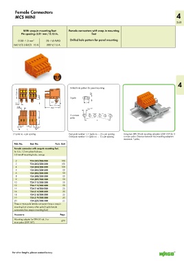
With snap-in mounting feet Female connectors with snap-in mounting
Pin spacing: 3.81 mm / 0.15 in. feet
0.08–1.5 mm 2 28–14 AWG Drilled hole pattern for panel mounting
160 V/2.5 kV/2 10 A 300 V/10 A
4
Drilled hole pattern for panel mounting
__>
<_ 13,4 _ __> 2-pole 3,5
4,5
4,1 <7>
3,2 ____> <
__> < < <__ 12 __>
3,81
___> < <____ 18,6 ____> 3,5 +0,1
____>
_ 3 or more
poles
<____ 18,6 _ <____________ L ___________>
81
1,5
> <_ _ 3, __> _ ( > 0,7
<_________L _______> <_
L = pole no. x pin spacing Even pole number : L = (pole no. – 2) x pin spacing Using two DIN 35-rail mounting adapters (209-137) for 3
Odd pole number: L = (pole no. – 1) x pin spacing or more poles. Distance between two mounting adapters:
maximum 7 poles.
Pole No. Item No. Pack. Unit
Female connector with snap-in mounting feet,
for 0.6–1.2 mm plate thickness,
3.5 mm Ø mounting holes, orange
2 734-202/008-000 100
3 734-203/008-000 100
4 734-204/008-000 100
5 734-205/008-000 50
6 734-206/008-000 50
8 734-208/008-000 50
9 734-209/008-000 50
10 734-210/008-000 50
12 734-212/008-000 50
14 734-214/008-000 25
16 734-216/008-000 25
18 734-218/008-000 25
19 734-219/008-000 25
20 734-220/008-000 25
Three or more pole female connectors have a snap-in
mounting foot at every other pole (2-pole female
connectors/two snap-in mounting feet)
Accessory Page
Mounting adapter for DIN 35 rail, 3 or 479
more poles (209-187)
For other lengths, please contact factory.