
Page 248 - Wago_PCB_TerminalBlocksConnectors_Volume2_2015_US
P. 248
Female Connectors with Push-Buttons
4 Pin Spacing: 3.5 mm, 3.81 mm
246 MCS MINI
● Universal connection for all conductor types
● Easy-to-use design does not require specialty tools
● Ability to wire while mated
● Simple, push-in terminations of solid and ferruled conductors
● Integrated test ports for testing parallel to conductor entry
● 100% protected against mismating
● Coding pins available
Technical data:
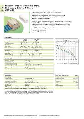
Pin Spacing 3.5 mm 3.81 mm Derating Curve
0.138 in. 0.15 in.
Ratings per IEC/EN 60664-1 IEC/EN 60664-1 2734-102 female connector with 734-132 male header
Pin spacing: 3.5 mm / Conductor size: 1.5 mm “f-st”
2
Overvoltage category III III II III III II Based on: EN 60512-5-2 / Reduction factor: 0.8
Pollution degree 3 2 2 3 2 2 Current in A
Rated voltage 160 V 160 V 320 V 160 V 160 V 320 V
Rated surge voltage 2.5 kV 2.5 kV 2.5 kV 2.5 kV 2.5 kV 2.5 kV 20
Nominal current 10 A 10 A 10 A 10 A 10 A 10 A
Approvals per UL/CSA UL/CSA 15
Use group UL 1059 B C D B C D
Rated voltage 300 V – 300 V 300 V – 300 V 10
Nominal current UL 10 A – 10 A 10 A – 10 A
Nominal current CSA 10 A – 10 A 10 A – 10 A 5
Conductor data:
Connection technology CAGE CLAMP S 0 10 20 30 40 50 60 70 80 90 100105
®
Conductor size: solid 0.2–1.5 mm 2 Ambient operating temperature in °C
Conductor size: fine-stranded 0.2–1.5 mm 2 2-, 4-, 6-, 12-, 24-pole Conductor rated current
Conductor size: fine-stranded 0.25–0.75 mm 2 (with insulated ferrule)
Conductor size: fine-stranded 0.25–1.5 mm 2 (with uninsulated ferrule)
AWG 24–16
Strip length 8–9 mm / 0.31–0.35 in.
Material data: MCS MINI accessories: Pages:
Material group I
Insulating material Polyamide 6.6 (PA 6.6) Marking accessories 570 – 573
Flammability rating per UL 94 0V Operating tools 272
Lower/Upper limit temperature -60 °C / +100 °C Direct marking 276 – 277
Clamping spring material Chrome nickel spring steel (CrNi) Test pin 568
Contact material Copper alloy Screws 576
Contact plating tin-plated Strain relief plates 275
MCS connectors are also available upon request with gold-plated or partially gold-plated contact surfaces.
Depending on the version requested, “item no. suffix . . . /010-000” is added to the “basic item no.”
The MULTI CONNECTION SYSTEM (MCS) is designed without breaking capacity for compliance with DIN EN 61984.
When used as intended, these connectors shall not be connected/disconnected when live or under load. The circuit
design should ensure header pins, which can be touched, are not live when unmated.
Additional approvals and corresponding ratings can be found at www.wago.com. For additional technical information, see Section 13.