
Page 30 - Wago_PCB_TerminalBlocksConnectors_Volume2_2015_US
P. 30
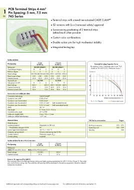
PCB Terminal Strips 4 mm         2
    1 Pin Spacing: 5 mm, 7.5 mm
    28 745 Series
                                              ●  Terminal strips with screwdriver-actuated CAGE CLAMP ®

                                              ●   4 versions with Ex e (increased safety) approval
                                              ●  Space-saving positioning of 2 terminal strips
                                                behind each other possible

                                              ●  Custom color combinations
                                              ●  Double solder pins for high mechanical stability

                                              ● Integrated testing tap


        Technical data:
                                                  7.5 mm
                                   5 mm
        Pin Spacing               0.197 in.       0.295 in.                          Current-Carrying Capacity Curve
                                                                                                          2
        Ratings per            IEC/EN 60664-1   IEC/EN 60664-1                   Pin spacing: 5 mm / Conductor size: 4 mm  “f-st”
                                                                                  Based on: EN 60512-5-2 / Reduction factor: 1
        Overvoltage category   III  III   II   III  III   II
        Pollution degree       3    2     2    3    2     2                     Current in A
        Rated voltage        320 VDC320 VDC630 VDC 500 V 630 VDC 1000 V
        Rated surge voltage   4 kV  4 kV  4 kV  6 kV  6 kV  6 kV                40
        Nominal current       32 A  32 A  32 A  32 A  32 A  32 A
        Approvals per             UL/CSA          UL/CSA                        30
        Use group UL1059       B    C     D    B    C     D
        Rated voltage         300 V  –   300 V  300 V 150 VDC  300 V            20
        Nominal current UL    20 A  –    10 A  20 A  20 A  10 A
        Nominal current CSA   20 A  –    10 A  20 A  20 A  10 A                 10
        Conductor and solder pin data:
        Connection technology       CAGE CLAMP ®                                 0  10  20  30  40  50  60  70  80  90 100105
        Conductor size: solid       0.08–4 mm 2                                              Ambient operating temperature in °C
        Conductor size: fine-stranded  0.08–4 mm 2                                2-, 4-, 6-, 12-pole  Conductor rated current
        Conductor size: fine-stranded  0.25–2.5 mm 2  (with insulated ferrule)
        Conductor size: fine-stranded  0.25–2.5 mm 2  (with uninsulated ferrule)
        AWG                         28–12
        Strip length                8–9 mm / 0.31–0.35 in.
        Conductor entry angle       45° to PCB
        Solder pin: length/width    4 mm / 0.8 x 1.2 mm
        Solder pin: drilled hole diameter  1.5 +0.1  mm
        Material data:                                                          745 Series accessories:    Pages:
        Material group              I
        Insulating material         Polyamide 6.6 (PA 6.6)                      Marking accessories     570 – 573
          Flammability rating per UL 94  0V                                     Operating tools         556 – 559
        Lower/Upper limit temperature  -60 °C / +105 °C                         Test plug                    568
        Clamping spring material    Chrome nickel spring steel (CrNi)
        Contact material            Electrolytic copper (E )
                                                Cu
        Contact plating             tin-plated
        Technical data for Ex e II (4) versions:
                                                  7.5 mm
                                   5 mm
        Pin Spacing               0.197 in.       0.295 in.
        Ratings per
        ATEX: PTB 06 ATEX 1014 U    IECEx: IECEx PTB 06.0039 U
        Rated voltage             176 VDC          352 V
        Nominal current            27 A            27 A

        Note on UL approval for 600 V:
        The conductor entry is for field and factory wiring and meets spacing requirements for 600 V UL (Use Group C). The solder
        pins are for factory wiring only. The suitability and spacing shall be evaluated in the end-use equipment, based on relevant
        end-product standard.


       Additional approvals and corresponding ratings can be found at www.wago.com   For additional technical information, see Section 13.