
Page 324 - Wago_PCB_TerminalBlocksConnectors_Volume2_2015_US
P. 324
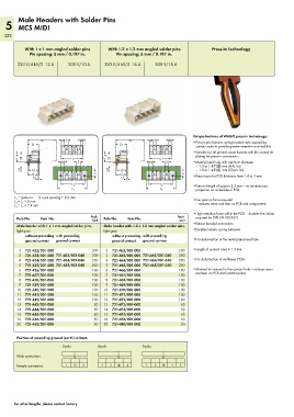
Male Headers with Solder Pins
   5 MCS MIDI
   322


           With 1 x 1 mm angled solder pins  With 1.2 x 1.2 mm angled solder pins      Press-In Technology
             Pin spacing: 5 mm / 0.197 in.      Pin spacing: 5 mm / 0.197 in.

        320 V/4 kV/2  12 A   300 V/10 A    320 V/4 kV/2  16 A   300 V/15 A


                                                                               Unique features of WAGO press-in technology:
            <________30________>  4,15  4,1     <________30________>  4,15  4,1  • Press-in pin features spring-loaded style expanding
            <_12_>                              <_12_>                          contact zone to provide greater retention and stability
        (_ 11,4_)  <  7,5  <__________>     (_ 11,4_)  <  7,5  6,5  L 1  5     • Suitable for all printed circuit boards with the correct tin
                                                                                plating for press-in connectors
                                                              <__________>
                              L 1
                                                                               • Metal-plated hole with optimum diameter
                          6,5
                                5
                                                                                – 1.0 or 1.45 –0.00  mm (Chem. Sn)
         3,8  __>  (_10_)                    3,8  __>  (_10_)                   – 1.0 or 1.45   mm (HAL Sn)
            <_12_>                      5       <_12_>                      5  • Press-in pin for PCB thickness from 1.4 to 3 mm
              1,5                                 1,5
              _> <                                _> <
                          <___________>                      <___________>     • Press-in length of approx 3.2 mm — no unnecessary
                                                                  L 2
                              L 2
                        <________________>                  <________________>  projection on underside of PCB
                                                                  L 3
                              L 3

       L  = (pole no. – 1) x pin spacing + 8.2 mm
       1
       L  = L  + 5 mm                                                          • low press-in force required
          1
       2
       L  = L  + 7.4 mm                                                         – reduces wear and tear on PCB and components

          2
       3
                                                                               • High retention force within the PCB — doubles the values
        Pole No.  Item No.            Pack.   Pole No.  Item No.         Pack.   required by DIN EN 60352-5
                                       Unit
                                                                          Unit
        Male header with 1 x 1 mm angled solder pins,   Male header with 1.2 x 1.2 mm angled solder pins,   • Robust bonded connection
        light gray                         light gray                          • Excellent elastic spring behavior
           without preceding  with preceding   without preceding  with preceding
           ground contact  ground contact     ground contact  ground contact   • No deformation of the metal-plated end hole

         2  721-432/001-000           200   2  721-462/001-000           200   • Length of contact area ≥ 1.3 mm
         3  721-433/001-000 721-433/001-040   200   3  721-463/001-000 721-463/001-040  200
         4  721-434/001-000 721-434/001-040   200   4  721-464/001-000 721-464/001-040  200  • No deformation of multilayer PCBs
         5  721-435/001-000 721-435/001-040   200   5  721-465/001-000 721-465/001-040  200
         6  721-436/001-000           100   6  721-466/001-000           100   • Minimal tin removal in the contact hole — reduces wear
         7  721-437/001-000           100   7  721-467/001-000           100    and tear on PCB and contact points
         8  721-438/001-000           100   8  721-468/001-000           100
         9  721-439/001-000           100   9  721-469/001-000           100
        10  721-440/001-000           100  10  721-470/001-000           100
        11  721-441/001-000           100  11  721-471/001-000           100
        12  721-442/001-000           100  12  721-472/001-000           100
        13  721-443/001-000            50  13  721-473/001-000            50
        14  721-444/001-000            50  14  721-474/001-000            50
        15  721-445/001-000            50  15  721-475/001-000            50
        16  721-446/001-000            50  16  721-476/001-000            50
        20  721-450/001-000            50  20  721-480/001-000  1  3  3   50
        Position of preceding ground (earth) contact:
                                                            1
                                          1
                          3-pole         4-pole  3  3      5-pole  2  3  4
        Male connectors
        Female connectors   1  3   3      1   2  3  4       1   2  3  4   5
                            1  2  3   4   1   2  3  4   5


       For other lengths, please contact factory.
                            1  2  3   4  5