
Page 395 - Wago_PCB_TerminalBlocksConnectors_Volume2_2015_US
P. 395
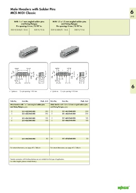
Male Headers with Solder Pins
          MCS MIDI Classic                                                                                         6
                                                                                                                   393

             With 1 x 1 mm angled solder pins   With 1.2 x 1.2 mm angled solder pins
                    and fixing flanges                 and fixing flanges
               Pin spacing: 5 mm / 0.197 in.      Pin spacing: 5 mm / 0.197 in.

          320 V/4 kV/2  12 A   300 V/10 A     320 V/4 kV/2  16 A  300 V/15 A


             > 4,5<     > 5,1<                   > 4,5<    > 5,1<
                 <_____L _____>                     <_____L _____>
             2,9  <_  _                  <      2,9  <_  _                   <
            <                <  6,5<     8,4   <                 <  6,5<     8,4
              >                >  <  1,8  >      >                >  <  1,8  >
           3,8  __>         3,55  __ _>  __>  __>  <  3,8  __>  3,55  __ _>  __>  __>  <
              3  >  5 <          3,8  >  6,9 <   3  >  5 <          3,8  >  6,9 <
              >  <                  (_10_)       >  <                  (_10_)
              >  6,5 <  >  7,1 <   <_ 12_>        >  6,5 <  >  7,1 <  <_ 12_>
                                                                                                                    6

         L = (pole no. – 1) x pin spacing + 8.2 mm   L = (pole no. – 1) x pin spacing + 8.2 mm


          Pole No.  Item No.         Pack. Unit  Pole No.  Item No.     Pack. Unit
          Male header with 1 x 1 mm angled solder pins   Male header with 1.2 x 1.2 mm angled solder pins
          and fixing flanges, gray           and fixing flanges, gray
           2        231-432/040-000      200   2       231-462/040-000      200
           3        231-433/040-000      200   3       231-463/040-000      200

           5        231-435/040-000      100   5       231-465/040-000      100
           6        231-436/040-000      100   6       231-466/040-000      100


          14        231-444/040-000      50  14        231-474/040-000      50


          For cutout dimensions, see page 491, Table 4.  For cutout dimensions, see page 491, Table 4.


          Female connectors with locking devices are not suitable for this type of application.
          For other lengths, please contact factory.