
Page 394 - Wago_PCB_TerminalBlocksConnectors_Volume2_2015_US
P. 394
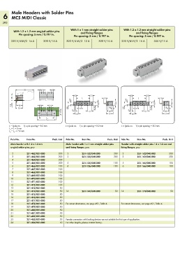
Male Headers with Solder Pins
   6 MCS MIDI Classic
   392

                                              With 1 x 1 mm straight solder pins   With 1.2 x 1.2 mm straight solder pins
          With 1.2 x 1.2 mm angled solder pins      and fixing flanges                  and fixing flanges
             Pin spacing: 5 mm / 0.197 in.      Pin spacing: 5 mm / 0.197 in.      Pin spacing: 5 mm / 0.197 in.

        320 V/4 kV/2  16 A   300 V/15 A    320 V/4 kV/2  12 A   300 V/10 A    320 V/4 kV/2  16 A   300 V/15 A


           <________30________>  4,1  5  4,1
         <                                     > 4,5<    >  5,1<                  > 4,5<     > 5,1<
         7,5                                      <              >  5 <              <____ ______>_____L _____>  >  5 <
                                                  <____ ______>_____L _____>
                                                                                     <
                          <_____ L _____>     2,9  <_  _                   <      2,9  <_  _                   <
                                             <                <  6,5 <     8,4   <                <  6,5 <     8,4
        3,8  ___>  (_10_)  6,5   5             >                                  >
           <_12_>                           3,8  __>  >  5 <  3,55  ___>  >  1,8  <  >  3,8  __>  >  5 <  3,55  ___>  >  1,8  <  >
                                                                                                          __>
                                                                      __>
                                               3                                  3
                                        5      >  <    >  7,1 <     >  6,9 <       >  <    >  7,1 <     >  6,9 <
                                               >  6,5 <              <_ 12_>       >  6,5 <             <_ 12_>
                          <___________>
                               L 1
                         <________ _______>
                               L 2
       L = (pole no. – 1) x pin spacing + 8.2 mm   L = (pole no. – 1) x pin spacing + 8.2 mm   L = (pole no. – 1) x pin spacing + 8.2 mm
       L  = L + 5 mm
       1
       L  = L  + 7.4 mm
          1
       2
        Pole No.  Item No.        Pack. Unit  Pole No.  Item No.     Pack. Unit  Pole No.  Item No.      Pack. Unit
        Male header with 1.2 x 1.2 mm      Male header with 1 x 1 mm straight solder pins   Header with straight solder pins 1.2 x 1.2 mm and
        angled solder pins, gray           and fixing flanges, gray           fixing flanges, gray
         2        231-462/001-000     200   2        231-132/040-000     200   2        231-162/040-000      200
         3        231-463/001-000     200   3        231-133/040-000     200   3        231-163/040-000      200
         4        231-464/001-000     200
         5        231-465/001-000     200   5        231-135/040-000     100   5        231-165/040-000      100
         6        231-466/001-000     100   6        231-136/040-000     100   6        231-166/040-000      100
         7        231-467/001-000     100
         8        231-468/001-000     100
         9        231-469/001-000     100
        10        231-470/001-000     100
        11        231-471/001-000     100
        12        231-472/001-000     100
        13        231-473/001-000      50
        14        231-474/001-000      50  14        231-144/040-000      50  14        231-174/040-000      50
        15        231-475/001-000      50
        16        231-476/001-000      50
        17        231-477/001-000      50
        18        231-478/001-000      50  For cutout dimensions, see page 491, Table 4.  For cutout dimensions, see page 491, Table 4.
        19        231-479/001-000      50
        20        231-480/001-000      50
        21        231-481/001-000      50
        22        231-482/001-000      50
        23        231-483/001-000      50  Female connectors with locking devices are not suitable for this type of application.
        24        231-484/001-000      50  For other lengths, please contact factory.