Page 469 - Wago_PCB_TerminalBlocksConnectors_Volume2_2015_US
P. 469

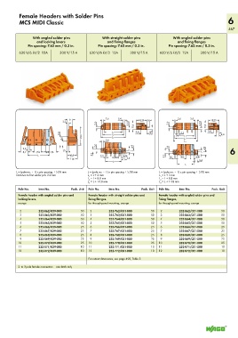
Female Headers with Solder Pins
           MCS MIDI Classic                                                                                        6
                                                                                                                   467

                  With angled solder pins           With straight solder pins           With angled solder pins
                   and locking levers                  and fixing flanges                 and fixing flanges
               Pin spacing: 7.62 mm / 0.3 in.     Pin spacing: 7.62 mm / 0.3 in.     Pin spacing: 7.62 mm / 0.3 in.

           630 V/6 kV/2  12A   300 V/15 A     630 V/6 kV/2  12A   300 V/15 A     630 V/6 kV/2  12A   300 V/15 A


                                                      2,6
                                                                                          2,6
                                   <  6 <          >  <__   3,4  <   <18,25> 5 <       >  <__   3,4  <   <18,25>
                                                                                                __>
                                                            __>
                                2,2                                 <                                   <
                                __>  <           2,6  <__        3,55  <___  11,6  <  2,6  <__       3,55  <___  11,6
                                                                                                         9,8
                                                                     9,8
                                                     <_____ L 1_____>
                                                                                           2,2
                               9,8                >  <______L 2_______>  >  >  ___>  <  3,95  __>  >  >  <__  >  >  ___>  < 4,4
                                4,4 <__  <_  ____ 21,6 ____>  > <_______ _L 3________>  <_______ _L 3________>  (_  __>
                                                                                         <_____ L 1_____>
                                                                                        <______L 2_______>
                                                      2,6
                                                     <__
                                >  >      <      2,6  <__         <  4,9             2,6
            2,2  <                              <                   <__             <  <__            <  4,9  <__   6
            __>
          >  8,2 < > 7,62 ( ) 5,08  <  1,5  <     >               7                                   7
                             •  7,6
                                __>
                                                                                      >
               <______  L  ______>  <10,8>     5,1  _>  2,2    5,08  >  >          5,1  _>  2,6  7,62  5,08  >  >
                                   <11,6 >         __>  <  > 7,62  > <  <_ 3,4        __>  < ___>  <___ 3,4
                                                      <____L _ _____>                            >  <__
                                                                                          <____ L ____>
         L = (pole no. – 1) x pin spacing + 5.08 mm   L = (pole no. – 1) x pin spacing + 5.08 mm   L = (pole no. – 1) x pin spacing + 5.08 mm
         Distance to first solder pin: 2.2 mm  L  = L + 3 mm                     L  = L + 3 mm
                                             1
                                                                                 1
                                             L  = L + 8.8 mm                     L  = L + 8.8 mm
                                             2
                                                                                 2
                                             L  = L + 14.8 mm                    L  = L + 14.8 mm
                                                                                 3
                                             3
          Pole No.  Item No.         Pack. Unit  Pole No.  Item No.     Pack. Unit  Pole No.  Item No.     Pack. Unit
          Female header with angled solder pins and    Female header with straight solder pins and    Female header with angled solder pins and
          locking levers,                    fixing flanges,                    fixing flanges,
          orange                             for through-panel mounting, orange  for through-panel mounting, orange
           2        232-862/039-000      50   2        232-762/031-000      50   2         232-862/031-000      50
           3        232-863/039-000      50   3        232-763/031-000      50   3         232-863/031-000      50
           4        232-864/039-000      50   4        232-764/031-000      50   4         232-864/031-000      50
           5        232-865/039-000      50   5        232-765/031-000      50   5         232-865/031-000      50
           6        232-866/039-000      25   6        232-766/031-000      25   6         232-866/031-000      25
           7        232-867/039-000      25   7        232-767/031-000      25   7         232-867/031-000      25
           8        232-868/039-000      25   8        232-768/031-000      25   8         232-868/031-000      25
           9        232-869/039-000      25   9        232-769/031-000      25   9         232-869/031-000      25
          10        232-870/039-000      25  10        232-770/031-000      25  10         232-870/031-000      25
          11        232-871/039-000      10  11        232-771/031-000      10  11         232-871/031-000      10
          12        232-872/039-000      10  12        232-772/031-000      10  12         232-872/031-000      10
                                             For cutout dimensions, see page 490, Table 3.
          2- to 3-pole female connectors – one latch only
   464   465   466   467   468   469   470   471   472   473   474