
Page 534 - Wago_PCB_TerminalBlocksConnectors_Volume2_2015_US
P. 534
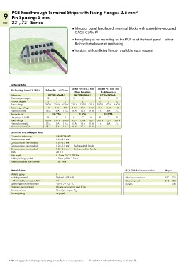
PCB Feedthrough Terminal Strips with Fixing Flanges 2.5 mm
                                                                                      2
   9 Pin Spacing: 5 mm
   532 231, 731 Series

                                              ●  Modular panel feedthrough terminal blocks with screwdriver-actuated
                                                CAGE CLAMP   ®
                                              ●  Fixing flanges for mounting on the PCB or at the front panel – either
                                                flush with enclosure or protruding

                                              ●  Versions without fixing flanges available upon request


        Technical data:

        Pin Spacing: 5 mm / 0.197 in.  Solder Pin 1 x 1.2 mm  Solder Pin 1 x 1.2 mm   Angled Pin 1 x 1 mm
                                                Flush Mounting  Flush Mounting
        Ratings per            IEC/EN 60664-1   IEC/EN 60664-1  IEC/EN 60664-1
        Overvoltage category   III  III   II   III  III   II   III  III   II
        Pollution degree       3    2     2    3    2     2    3     2    2
        Rated voltage        320 V  320 V  630 V  320 V  320 V  630 V  320 V  320 V  630 V
        Rated surge voltage   4 kV  4 kV  4 kV  4 kV  4 kV  4 kV  4 kV  4 kV  4 kV
        Nominal current       16 A  16 A  16 A  16 A  16 A  16 A  5 A  5 A  5 A
        Approvals per             UL/CSA          UL/CSA          UL/CSA
        Use group UL 1059      B    C     D    B    C     D    B    C     D
        Rated voltage         300 V 150 V  300 V  300 V 150 V  300 V  300 V 150 V  300 V
        Nominal current UL    15 A  15 A  10 A  15 A  15 A  10 A  5 A  5 A  5 A
        Nominal current CSA   15 A  15 A  10 A  15 A  15 A  10 A  5 A  –  –
        Conductor and solder pin data:
        Connection technology       CAGE CLAMP ®
        Conductor size: solid       0.08–2.5 mm 2
        Conductor size: fine-stranded  0.08–2.5 mm 2
        Conductor size: fine-stranded  0.25–1.5 mm 2  (with insulated ferrule)
        Conductor size: fine-stranded  0.25–2.5 mm 2  (with uninsulated ferrule)
        AWG                         28–14
        Strip length                8–9 mm / 0.31–0.35 in.
        Solder pin: length/width    4.7 mm / 0.8 x 1.3 mm
        Solder pin: drilled hole diameter  1.8 +0.1  mm

        Material data:                                                          231, 731 Series accessories:  Pages:
        Material group              I
        Insulating material         Nylon 6.6 (PA 6.6)                          Marking accessories     570 – 573
          Flammability rating per UL 94  0V                                     Operating tools         556 – 558
        Lower/Upper limit temperature  -60 °C / +105 °C                         Screws                       576
        Clamping spring material    Chrome nickel spring steel (CrNi)
        Contact material            Electrolytic copper (E )
                                                Cu
        Contact plating             tin-plated


       Additional approvals and corresponding ratings can be found at www.wago.com.   For additional technical information, see Section 13.