Page 535 - Wago_PCB_TerminalBlocksConnectors_Volume2_2015_US
P. 535

"

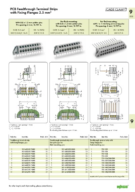
          PCB Feedthrough Terminal Strips
          with Fixing Flanges 2.5 mm         2                                                                     9
                                                                                                                   533

                                                      For flush mounting                 For flush mounting,
               With 0.8 x 1.3 mm solder pins      with 0.8 x 1.3 mm solder pins    with 1 x 1 mm long wire-wrap pins
               Pin spacing: 5 mm / 0.197 in.      Pin spacing: 5 mm / 0.197 in.       Pin spacing: 5 mm / 0.197 in.

             0.08–2.5 mm 2     28–14 AWG        0.08–2.5 mm 2     28–14 AWG        0.08–2.5 mm 2     28–14 AWG
          320 V/4 kV/2  16 A   300 V/10 A     320 V/4 kV/2  16 A  300 V/10 A     320 V/4 kV/2  5 A    300 V/5 A


                                0,3                       <_15,5_>                       <____23____><_15,5_>
                                <_ 14__ ><__           <_14,3_>     <_ 14__ >         <_14,3_>  <  <      <  <_ 14__ >
                                                                                                >
                                                                                               1
                   4,7<       1  <  >  _               4,7        1  <  >  _            6,3  >  __>  <   3,55  ___>  1  <  >  _
                                                                                               2,5
                   >                                   >                                                <
                 ______>  <                         ______>  <                                      _) 5,1
                 0,8 x1,3
                                                    0,8 x1,3
                      (8,7)(9,8)                         <13,4_) 5,1 <                               ( _ 7)
                                                                                            <________L________>
              3,4                 2,6             3,4                 2,6                    >  5  <
              __>  <  >  5  <  >  <__             __>  <  >  5  <  >  <__
              2,6  <__                <           2,6  <__               <
               >                                   >
                                     3,55  ___>                         3,55  ___>         <__________L 1 _________>
                <_____________ L 2 ____________>    <_____________ L 2 ____________>
                                                                                         <_____________L 2 ___________>
                                                                                           7,7         6,1
                                                                                                         3,2
                  <__________L 1 _________>           <__________L 1 _________>             4,8  1 >  < >  <___
                   <________L ________>                <________L________>
                   7,2         6,6                    7,2         6,6
                                                           1,3
                  >4,3 <  1,3  < >3,7 <              >4,3 <  __>  < >3,7 <
                        __>
                                     2,5  <__
               5,1<                     ( 7 )      <                    2,5  <__        5,1 <                2,5  __  <
               >                      _ )          7                     >  5,1 <                            >
                                                   >                       >            >                           9
         L = (pole no. x pin spacing) + 3 mm   L = (pole no. x pin spacing) + 3 mm   L = (pole no. x pin spacing) + 3 mm
         L  = L + 5.8 mm                     L  = L + 5.8 mm                     L  = L + 5.8 mm
                                                                                 1
          1
                                             1
         L  = L  + 6.4 mm                    L  = L  + 6.4 mm                    L  = L  + 6.4 mm
                                             2
                                                1
                                                                                    1
                                                                                 2
          2
            1
                                             for mounting plate thickness up to 1.5 mm  for mounting plate thickness up to 1.5 mm
          Pole No.  Item No.         Pack. Unit  Pole No.  Item No.     Pack. Unit  Pole No.  Item No.     Pack. Unit
          Feedthrough terminal strip         Feedthrough terminal strip with    Feedthrough terminal strip with
          with fixing flanges, gray          fixing flanges for                 fixing flanges for
                                             flush mounting, gray               flush mounting, gray
           2        231-602/017-000      100   2       231-602/023-000      100   2        731-132              50
           3        231-603/017-000      50   3        231-603/023-000      50   3         731-133              50
           4        231-604/017-000      50   4        231-604/023-000      50   4         731-134              25
           5        231-605/017-000      50   5        231-605/023-000      50   5         731-135              25
           6        231-606/017-000      50   6        231-606/023-000      50   6         731-136/048-000      25
           7        231-607/017-000      50   7        231-607/023-000      50   7         731-137/048-000      25
           8        231-608/017-000      50   8        231-608/023-000      50   8         731-138/048-000      25
           9        231-609/017-000      25   9        231-609/023-000      25   9         731-139/048-000      10
          10        231-610/017-000      25  10        231-610/023-000      25  10         731-140/048-000      10
          11        231-611/017-000      25  11        231-611/023-000      25  11         731-141/048-000      10
          12        231-612/017-000      25  12        231-612/023-000      25  12         731-142/048-000      10
                                                                                models with 6 pins or more feature reinforcing profile


         For other lengths and inkjet marking, please contact factory.
   530   531   532   533   534   535   536   537   538   539   540