
Page 623 - Wago_PCB_TerminalBlocksConnectors_Volume2_2015_US
P. 623
13
621
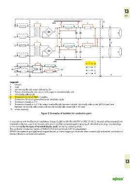
Legend:
1 Chassis
2 Load
3 non-intrinsically safe circuit defined by Um
4 Portion of intrinsically safe circuit, item proper is not intrinsically safe
5 Intrinsically safe circuit
6 Dimensions for which Table 5 applies
7 Dimensions for which general industrial standards apply
8 Dimensions based on 7.3
9 Dimensions based on 6.2.1 for output terminal blocks between isolated intrinsically safe circuits (d2 ≥ 6 mm) and
between intrinsically safe circuits and non-intrinsically safe circuits (d3 ≥ 50 mm)
10 where required
Figure 2: Examples of isolation for conductive parts
In accordance with the Electrical Installations Design Guideline DIN EN 60079-14 (VDE 0165-1), the ends of fine-stranded and
stranded conductors used in intrinsically safe circuits shall be protected against splaying of individual wires (e.g., via cable lugs
or ferrules) or by the type of terminal blocks used, but not by soldering alone.
The conductor introduction funnels of WAGO PCB terminal blocks fulfill this requirement.
WAGO recommends gas-tight tinned copper ferrules or tinned copper pin terminals when connecting fine-stranded conductors to
terminal blocks in corrosive atmospheres.
13