
Page 55 - Parker - P1/PD series medium duty axial piston pumps
P. 55
HY28-2665-01/P1/EN Medium Duty Axial Piston Pumps
Dimensional Data P1/PD Series
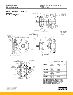
Pump Installation - P1/PD 075
End Port Case Drain Port 88.0 222.1 Max. Volume Stop
"D3"
“L” Control Option 22.5 (CCW Rotation)
Min. Volume Stop
(CW Rotation)
"BG" Gage Optional
Outlet Port
25.0
"D1" 95
Case Drain Port 93
To Load Sense Port "X"
Max. Volume Stop
113.0 (CW Rotation)
145.0 Min. Volume Stop
For Shaft & Flange
Pressure Compensator Dimensions, see page 52 287.2 Maximum (CCW Rotation)
Adjusting Screw Optional
Load Sense "D2"
Adj. Screw 127.7 Case Drain Port
CW Control 104.5 89.0
Location 86.0 3.9 136.0
CW Rotation Plug
Arrow
"X" Load
Sense Port
120
113 99.5
51.0
53.5
103.8
100.8
122
115
15.8 Nameplate
CCW Control Location 12.2
CCW Rotation Arrow
2X 44.1 "B" Outlet Port
(to Drain Ports) P1/PD 075 Port Sizes
36 52.5
SAE ISO BSP
2X 55˚
A Inlet 50mm 50mm —
code 61 C DN 51 B
2X 83.9 25.6
(to Drain Ports) 24.4 W Threads ½ - 13 M12 x 1.75 B —
UNC-2B C
21.45
B Outlet 25mm 25mm —
26.2
42.9 code 61 C DN25 B
13.1
Y Threads 6 - 16 M10 x 1.5 B —
W (4 Places) UNC-2B C
50.4 Y (4 Places)
49.6 BG SAE-4 D M12x1.5 A ¼" E
"A" Inlet Port
D1 D2 D3 SAE-12 D M27x2 A ¾" E
38.9 26.2 X SAE-4 D M12x1.5 A ¼" E
77.8 52.4
Note A: Metric o-ring boss port conform to ISO 6149-1
Note B: Metric 4-bolt flange port conforms to ISO 6162
Note C: Inch 4-bolt flange port conforms to SAE J518
Note D: Inch o-ring boss port conforms to SAE J514
Note E: BSP boss port conforms to ISO 228-1
Parker Hannifin Corporation
Hydraulic Pump Division
Marysville, Ohio USA 53