
Page 57 - Parker - P1/PD series medium duty axial piston pumps
P. 57
HY28-2665-01/P1/EN Medium Duty Axial Piston Pumps
Dimensional Data P1/PD Series
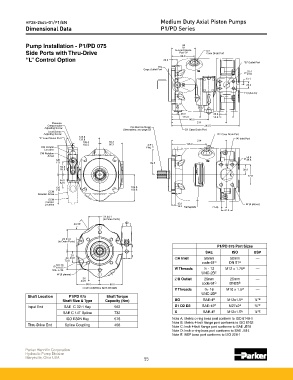
Pump Installation - P1/PD 075 94
92
to Load Sense D3
Side Ports with Thru-Drive Port "X" Case Drain Port
88.0
“L” Control Option 22.5
"B" Outlet Port
BG
Gage Outlet Port
25.4
24.6
13.1
26.2
Y (4 places)
25.0 26.2
113.0 52.4
145.0
Pressure 214
Compensator 263.5
For Shaft & Flange
Adjusting Screw Dimensions, see page 52 D1 Case Drain Port
Load Sense
Adjusting Screw D2 Case Drain Port
128.6
"X" Load Sense Port "A" Inlet Port
126.6 214
105.5 89.3
103.5 86.3 4.9 136.0
CW Control Plug
Location
CW Rotation
Arrow 50.4
120 49.6
113 99.5
52.0
50.0 38.9
77.8
54.5
52.5
120 103.8
115 100.8
CCW
Rotation Arrow
CCW
Control
Location 15.8 W (4 places)
12.2 Nameplate 21.45
42.9
2X 44.1
(to Drain Ports)
2X 55˚
2X 83.9
(to Drain Ports)
P1/PD 075 Port Sizes
SAE ISO BSP
2X
2X 44.9
A Inlet 50mm 50mm —
73.0
code 61 C DN 51 B
101.70
101.65 W Threads ½ - 13 M12 x 1.75 B —
SAE J744
UNC-2B C
W (6 places)
2X
B Outlet 25mm 25mm —
44.9
90.0 88.0 code 61 C DN25 B
CCW CONTROL NOT SHOWN
Y Threads 6 - 16 M10 x 1.5 B —
UNC-2B C
Shaft Location P1/PD 075 Shaft Torque
Shaft Size & Type Capacity (Nm) BG SAE-4 D M12x1.5 A ¼" E
Input End SAE C 32-1 Key 562 D1 D2 D3 SAE-12 D M27x2 A ¾" E
SAE C 14T Spline 732 X SAE-4 D M12x1.5 A ¼" E
ISO E32N Key 576 Note A: Metric o-ring boss port conform to ISO 6149-1
Note B: Metric 4-bolt flange port conforms to ISO 6162
Thru-Drive End Spline Coupling 458
Note C: Inch 4-bolt flange port conforms to SAE J518
Note D: Inch o-ring boss port conforms to SAE J514
Note E: BSP boss port conforms to ISO 228-1
Parker Hannifin Corporation
Hydraulic Pump Division
Marysville, Ohio USA 55