
Page 178 - Brass, Composite and Thermoplastic Fittings and Valves
P. 178
Catalog 3501E
Cartridges PMT Cartridges
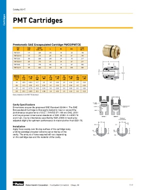
Prestomatic SAE Encapsulated Cartridge PMCE/PMTCE
PART TUBE CAVITY L M O.D. FLOW
NO. SIZE SIZE ±.002 DIA. D
PMTCE-4 1/4 .504 .64 .44 .56 .140
PMTCE-4-8 1/4 .775 .66 .42 .87 .140
PMTCE-6 3/8 .650 .84 .64 .75 .217
PMTCE-6-8 3/8 .775 .84 .64 .87 .217 L
PMTCE-8 1/2 .775 .98 .77 .87 .338 M
PMTCE-10 5/8 .925 1.07 .86 1.00 .398
D
O.D.
NOMINAL D1 L1 R1 R2 C1
TUBE OD (MM) D1 (IN) (MM) L1 (IN) (MM) R1 (IN) (MM) R2 (IN) (MM) C1 (IN)
(IN) ±.05 ±.002 MIN MIN ±.05 ±.002 ±.05 ±.002 ±.05 ±.002
1/4 12.8 0.504 12.7 0.5 0.5 0.02 0.5 0.02 0.5 0.02
3/8 16.5 0.65 16.5 0.65 0.5 0.02 0.5 0.02 0.5 0.02
1/2 19.7 0.775 19.8 0.78 0.5 0.02 0.5 0.02 0.5 0.02
5/8 23.5 0.925 22.4 0.88 0.8 0.03 0.5 0.02 0.8 0.03
Cavity material is to be 6061 T6 aluminum
APPLY FORCE
PMTCE
EXTERNAL PMTCE
Cavity Specifications O-RING
Dimensions are per the proposed SAE Standard J2494-4. The SAE CAVITY “POSITIVE STOP”
SHOULDER
Encapsulated Cartridge is thoroughly tested to meet or exceed the BODY
performance requirements of D.O.T. FMVSS 571.106 and SAE J2231
and the proposed dimensional standards of SAE J2494-4 in 6061-T6
aluminum. Cavity dimensions specified by SAE J2494-4 need tp be STEP 1 STEP 2 Optional
adjusted slightly for optimum performance in material other than 6061-T6. Construction
D1 D1
45
R1 C1
Installation
Apply force evenly over the top surface of the cartridge body 32
until the cartridge shoulder bottoms out on the top of the 32 L1 L1
cavity. The amount of force required will vary depending R2 R2
on the cartridge size and the material of the cavity.
Parker Hannifin Corporation | Fluid System Connectors | Otsego, MI D12