


Page 407 - Brass, Composite and Thermoplastic Fittings and Valves
P. 407
Catalog 3501E


            Tube Line Fabrication Guide

            for Leak Free Systems                                                                                      General Technical


            Every hydraulic, pneumatic and lubrication system   The most logical path should have the
            requires some form of tube line fabrication and fitting   following characteristics:
            installation for completion. Proper fabrication and
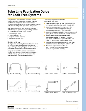
            installation are essential for the overall efficiency, leak free   ■   Avoid excessive strain on joint — A strained joint
            performance, and general appearance of any system.    will eventually leak. (See Figures A14 through A21.)
                                                               ■   Allow for expansion and contraction — Use
            Start by planning ahead. After sizing the tube lines   a “U” bend or a hose in long lines to allow for
            and selecting the appropriate style of fitting, consider   expansion and contraction. (See Figure A22.)
            the following in the design of your system:
                                                               ■   Allow for motion under load — Even some apparently
            1. Accessibility of joints                            rigid systems do move under load. (See Figure A23.)
            2. Proper routing of lines                         ■   Get around obstructions without using
            3. Adequate tube line supports                        excessive amount of 90° bends — Pressure
            4. Available fabricating tools                        drop due to one 90° bend is greater than that due
                                                                  to two 45° bends. (See Figures A24 and A25.)
            Routing of Lines                                   ■   Keep tube lines away from components that require
            Routing of lines is probably the most difficult yet most   regular maintenance. (See Figures A26 and A27.)
            significant of these system design considerations.   ■   Have a neat appearance and allow for
            Proper routing involves getting a connecting line from   easy troubleshooting, maintenance and
            one point to another through the most logical path.   repair. (See Figures A28 and A29.)

            Always try to leave fitting joints as accessible as
            possible. Hard to reach joints are hard to assemble
            and tighten properly. Inaccessible joints are also
            more difficult and time consuming to service.


            Fig. A14 — Correct Routing  Fig. A15 — Incorrect Routing  Fig. A18 — Correct Routing  Fig. A19 — Incorrect Routing


            Fig. A16 — Correct Routing  Fig. A17 — Incorrect Routing
                                                                Fig. A20 — Correct Routing  Fig. A21 — Incorrect Routing


                                                                                               (continued next page)


                       Parker Hannifin Corporation  |  Fluid System Connectors  |  Otsego, MI                  N7

