
Page 5 - Parker - Pressure Control Valves
P. 5
Catalog HY15-3502/US
Technical Tips Pressure Control Valves
CV
PRODUCT TYPES / APPLICATIONS
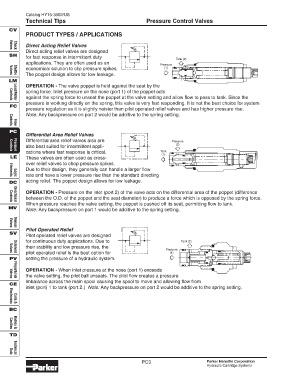
Direct Acting Relief Valves
Valves
Check
Direct acting relief valves are designed
SH
for fast response in intermittent duty
Tank (2)
applications. They are often used as an
Pressure
economical solution to clip pressure spikes. (1)
The poppet design allows for low leakage.
Shuttle
Valves
LM
OPERATION - The valve poppet is held against the seat by the
spring force. Inlet pressure on the nose (port 1) of the poppet acts
against the spring force to unseat the poppet at the valve setting and allow flow to pass to tank. Since the
Load/Motor
Controls
pressure is working directly on the spring, this valve is very fast responding. It is not the best choice for system
FC
pressure regulation as it is slightly noisier than pilot operated relief valves and has higher pressure rise.
Note: Any backpressure on port 2 would be additive to the spring setting.
Flow
Controls
PC
Differential Area Relief Valves
Differential area relief valves also are Pressure
(2)
also best suited for intermittent appli-
cations where fast response is critical. Tank
Pressure
Controls
(1)
LE These valves are often used as cross-
over relief valves to chop pressure spikes.
Due to their design, they generally can handle a larger flow
rate and have a lower pressure rise than the standard directing
Elements
Logic
acting relief. The poppet design allows for low leakage.
DC
OPERATION - Pressure on the inlet (port 2) of the valve acts on the differential area of the poppet (difference
between the O.D. of the poppet and the seat diameter) to produce a force which is opposed by the spring force.
Directional
When pressure reaches the valve setting, the poppet is pushed off its seat, permitting flow to tank.
Controls
MV
Note: Any backpressure on port 1 would be additive to the spring setting.
Valves
Manual
Pilot Operated Relief
SV
Pilot operated relief valves are designed
for continuous duty applications. Due to Tank (2)
their stability and low pressure rise, the
Pressure
pilot operated relief is the best option for (1)
Solenoid
Valves
PV setting the pressure of a hydraulic system.
OPERATION - When inlet pressure at the nose (port 1) exceeds
the valve setting, the pilot ball unseats. The pilot flow creates a pressure
Proportional
Valves
imbalance across the main spool causing the spool to move and allowing flow from
CE
inlet (port) 1 to tank (port 2.) Note: Any backpressure on port 2 would be additive to the spring setting.
Electronics
Coils &
BC
Cavities
Bodies &
TD
Technical
Data
PC3 Parker Hannifin Corporation
Hydraulic Cartridge Systems