
Page 6 - Parker - Pressure Control Valves
P. 6
Catalog HY15-3502/US
Technical Tips Pressure Control Valves
CV
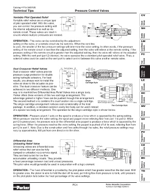
Ventable Pilot Operated Relief
Ventable relief valves are a unique type
of pilot operated relief. With this valve, Vent (2) (3) Outlet Check Valves
you can control the pressure setting with Press.
Inlet SH
the internal adjustment as well as via (1)
remote circuit. These valves are ideal in
Shuttle Valves
cirucits where multiple pressures are needed.
OPERATION - This valve can be controlled by the adjustment LM
setting on the valve, or a remote circuit via the vent line. When the vent line
is used, the smaller of the two pressure settings will determine the valve setting. In other words, if the pressure Load/Motor Controls
setting of the remote circuit is less than the adjusted setting, then the valve will relieve at the remote setting. If the
pressure setting of the remote circuit is greater than the adjusted setting, then the valve will relieve at the adjusted
FC
setting. With the vent port (port 2) blocked, the valve operates like a standard pilot operated relief valve. Thus, a
solenoid valve could be used on the vent port to select control between this valve another remote valve.
Flow Controls
PC
Dual Crossover Relief Valves A Control Valve B (2) (2)
Dual crossover relief valves provide RVA (1)
pressure surge protection for double Pressure Controls
acting hydraulic actuators. For best
results, you always want to install the Single LE
Cartridge Style
valve as close to the actuator as pos-
sible. The dual crossover feature can be RVB RVB Elements
A Motor B Logic
achieved in two different methods. One
way is to manifold two Differential Area Relief Valves into a single body. RVA DC
Parker offers three versions of this two cartridge arrangement. The
advantage gained is higher flows can be pushed through this arrangement. Directional
The second method is to combine this dual function into a single cartridge. RDH103 Series Controls
Relief Cartridge Valve (2 Ea.) Body
The single cartridge arrangement reduces cost considerably of the total
Two Cartridge Style
package. In addition, a standard common cavity line body can be used instead MV
of a special two body arrangement. The operation for the single cartridge style is shown below.
Manual Valves
OPERATION - Pressure at port 1 acts on the spool to produce a force which is opposed by the spring setting.
When pressure reaches the valve setting, the spool and poppet move relieving flow from port 1 to port 2. When SV
port 2 is pressurized, the pressure acts on the differential area poppet to produce a force which is opposed by the
spring force. When the pressure reaches the valve setting, the poppet is pushed off of its seat, relieving flow from Solenoid
port 2 to port 1. Note: Due to the construction and flow paths through the valve, the relief pressure settings may Valves
vary by approximately 300 psi from one direction to the other.
PV
Proportional
Differential Area Valves
Unloading Relief Valve
CE
Unloading valves are differential area Pressure (2) (3) Tank
relief valves that can also be fully Pilot Electronics
dumped or unloaded via a remote signal. (1) Coils &
They are best suited for low flow
accumulator unloading circuits. They provide BC
a fixed percentage between load and unload pressures.
Bodies & Cavities
This pilot valve would generally be used in conjunction with a logic element.
OPERATION - The fixed differential is provided by the pilot piston which has greater area than the dart seat. With TD
its greater area, the piston is able to hold the dart off its seat, permitting flow from pressure to tank, until pressure
Technical Data
on the pilot piston falls below the fixed percentage of the valve settings.
PC4 Parker Hannifin Corporation
Hydraulic Cartridge Systems