
Page 337 - Parker - Parker Pneumatic
P. 337
Catalog PDN1000-3US Actuators – Accessories
Parker Pneumatic Basic Air-Oil Circuit Operation
4TK Air-Oil Tanks
4TK Air-Oil Tanks – For Smoother Hydraulic Flow
Parker Air-Oil tanks provide a means to convert shop
air pressure into hydraulic pressure. Compressed air is applied Opt. Opt.
directly to the oil in the air-oil tank to convert it into hydraulic
pressure. The hydraulic pressure is at a 1-to-1 Air Air
ratio, i.e. 80 PSIG air produces 80 PSIG hydraulic pressure. Oil Valve For Adjusting Oil
Tank Oil Level
All Parker Air-Oil tanks have a fiberglass tube which shows the Advance Return
Tank
Tank
proper oil level. They also contain two fluid flow baffles. The top
baffle disperses the incoming air over the surface of the oil in
such a way to avoid agitation and aeration. The bottom baffle
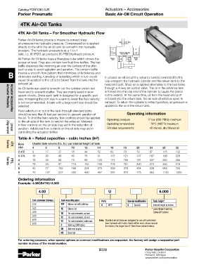
B insures a smooth flow pattern that minimizes oil turbulence and In a basic air-oil circuit the advance tank is connected to the
eliminates swirling, funneling or splashing which in turn could
cause oil aeration or the oil to be blown from the tank into the cap end port of a hydraulic cylinder and the return tank to the
exhaust air. head end port. Shop air is applied alternately to the two tanks
Air-Oil tanks are used to smooth out the cylinder piston rod through a 4-way air control valve. The oil in the advance tank
travel and to prevent chatter. They are mainly used in slow is forced into the cap end of the cylinder to cause the piston
speed circuits. Since each tank is designed for a specific port rod to extend. At the same time, oil from the head end port
size, increasing the port size in a tank to lower the fluid velocity is forced into the return tank, the air side of which is open to
is not recommended. A tank with a larger port size should be exhaust. To return the cylinder to retract position, air pressure is
selected. applied to the oil in the return tank.
Actuator Products
Fluid velocity in or out of the tank through standard ports
should be less than 6 feet per second to prevent aeration of Operating information
Actuator Accessories
the oil. To limit the fluid velocity, flow controls should be applied
to the air side of the tank to restrict the exhaust. Metered- Operating pressure 17 bar (250 PSIG) maximum
in flow controls on the air side may aid in the reduction of Operating temperature 74°C (165°F) maximum
aeration. Additional flow controls on the oil side may aid in Filtration requirements 40 micron, dry filtered air
controlling the actuator motion.
Linear
Alignment
Table A – Rated capacities - cubic inches (in )
3
Bore Usable tank volume (Cu. In.) per internal height of tank
size 4 6 8 10 12 14 16 18 20 24 28 32
4TK
Series
2-1/2 9 17 27 35 44 52 62 70 79 97 115 132
3-1/4 16 30 46 60 76 91 107 121 137 167 198 228
4 18 33 58 73 98 120 144 166 191 237 283 330
5 29 53 92 116 155 189 228 261 300 373 446 519
PRL
Series
6 42 77 133 168 224 273 329 378 434 539 645 750
8 75 137 237 300 400 487 587 675 775 963 1150 1338
Ordering information
Example: 4.00CB4TKU 6.000
4.00 CB 4TK U 6.000
Tank diameter (inches) Tank mounting style Ports Special modification Tank height*
2.50 TEF Sleeve nut with side tap U NPTF S Special Internal height in inches
3.25 TE Sleeve nut * Less than 4 Inches,
4.00 TB Tie rods extended, air end Consult Factory
5.00 TC Tie rods extended, oil end
6.00 TD Tie rods extended, both ends Note: Standard air-oil tanks are designed for use with petroleum
8.00 C Side lug (3MA style) base hydraulic oil. If other fluids will be used, please consult
the factory. For larger than 8" Bore Sizes consult factory.
CB Side end angles
NB Base bar
For ordering purposes, when special options or common modifications are requested, the factory will assign a sequential part
number in place of the model number.
B336 Parker Hannifin Corporation
Pneumatic Division
Richland, Michigan
www.parker.com/pneumatics