
Page 359 - Parker - Parker Pneumatic
P. 359
Catalog PDN1000-3US Electronic Sensors
Parker Pneumatic How to Specify Sensors for 2A, 2AN
How to specify EPS sensors
Parker EPS proximity sensors may be ordered on 5) Specify letter prefix “H” for EPS-7, “D” for EPS-6, “R” for
2A, 2AN, 4MA and 4MAJ Series cylinders as follows: EPS-5, “F” for CLS-1, or “B” for CLS-4, then fill in the
1) Complete the basic cylinder model number. four fields specifying port location, sensor orientation and
actuation point for both head and cap. If only one sensor is
2) Place an “S” in the model number to denote sensors used, place “XXXX” in the unused fields.
and/or special features.
3) Mounting styles D, DB, JB, or HB should be used with Example = H13CGG-XXXX denotes a sensor on the head
end only, EPS-7
caution because of possible mounting interferences.
Consult bulletin 0840-G-E1 for additional information. Example = BXXXX-42BGG denotes a sensor on the cap
end only, CLS-4
4) Special modifications to cylinders other than sensors must
have a written description.
B
Head end Cap end
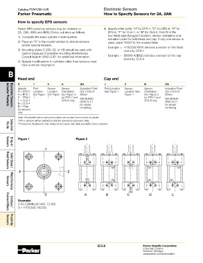
R 1 3 A GG 4 2 B GG
Specify: Port Sensor Sensor Actuation Point Port Location Sensor Sensor Actuation Point
R = EPS-5 Location Location Orientation GG = End of See Figure 1. Location See Orientation GG = End of
H = EPS-7 See Figure See Figure See Figure 2 Stroke Figure 1. See Figure 2 Stroke
D = EPS-6 1. 1. for EPS-7 and See Bulletin for EPS-7 and See Bulletin
F = CLS-1 EPS-6 only. 0840-G-E1 EPS-6 only. 0840-G-E1
B = CLS-4 for stroke for stroke
|N = Prep remaining. remaining.
Actuator Products
Electronic Sensors
for sensors
only
Note: All specified sensor and port locations are as seen from rod end of cylinder.
*EPS-5 sensors will be oriented so that the connectors face each other.
**Consult the Wadsworth, Ohio facility for this option with 4MA and 4MAJ Series cylinders.
Guide
Selection
Figure 1 Figure 2
Sensors
Drop-in
1
Solid State /
Reed Sensors
4 2
Sensors
Weld Immune
3 A B C D E
Example:
4.00 CJ4MAUS14AC 12.000
S = H13CGG-13CGG
Cordset /
Connect Block
Sensors
Proximity
B358 Parker Hannifin Corporation
Pneumatic Division
Richland, Michigan
www.parker.com/pneumatics