
Page 7 - Parker - Bodies and Cavities
P. 7
Catalog HY15-3502/US
Technical Tips Bodies and Cavities
CV
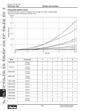
PRESSURE DROP CHART
The following charts outline the pressure drop through the Parker Cartpak bodies.
The pressure drop is minus the cartridge valve.
Valves
Check
SH PSI Bar
1200 83
Shuttle
Valves
1000 69
LM 8
P) 800 55
Pressure Drop ( 600 41
Controls
Load/Motor
FC 1
Flow
Controls
PC
400 28
6
7
Pressure
Controls
200 14
LE 4
5
2
3
0
LPM 19 38 57 76
0
Elements
Logic
GPM 5 10 15 20
DC Flow (Q)
Body Orientation P T A B
Directional
Controls
MV
BD03-PN Upright 1 2 3 3
Inverted 2 1 3 3
Valves
Manual
BD03-PT Upright 3 3 3 3
SV
Inverted 3 3 3 3
BD03-ABN Upright 3 3 4 4
Inverted 3 3 4 4
Solenoid
Valves
PV
BD03-ABT Upright 3 3 3 3
Inverted 3 3 3 3
BD03-ABX Upright 5 5 3 3
Valves
Proportional
CE
BD03-PNR Upright 6 3 3 3
BD03-PNS Upright 7 3 3 3
Coils &
Electronics
BD03-DDX Upright 3 3 1 1
BC
BD03-BDA Upright 6 3 3 3
BD03-ADB Upright 6 3 3 3
Cavities
Bodies &
TD
BD03-PN2 Upright 8 3 3 3
Inverted 3 8 3 3
Technical
Data
BC5 Parker Hannifin Corporation
Hydraulic Cartridge Systems