
Page 8 - Clippard - Pneumatic Modules
P. 8
PNEUMATIC MODULES
VA-023 & CM-023 Special Features
E F Maintained Output occurs as long as both palm buttons are held. Release of either button terminates the output
(shipped in this configuration).
How: Connect E to F using a piece of 5/32” O.D. tubing as a jumper
F
Momentary Output gives a single output pulse that is about 50 ms in duration.
How: Plug E with 5/32” Push-Quick Plug (11755 screw plug if using CM-023); F is open
E F Cancelable Output terminates the output after a Normally-Open 3-way limit valve has been tripped, even if both
palm buttons are held.
How: Interpose Normally-Open 3-way valve or other circuit function
Cancel Output after Time Delay is a variation of Cancelable Output (above) where pneumatic delay valve, such
as Clippard’s Model R-331, is set to cancel the output after a designated time interval has elapsed regardless of
E F how long the buttons are held.
How: Interpose Normally-Open 3-way delay valve (see R-331)
It is the user’s responsibility to determine which special
feature can be safely used in their particular application.
Because of the variety of applications for this equipment,
detailed instructions cannot be given for each possible
use. Users are warned that improper application, use,
installation, maintenance and/or alterations to this Circuit Operation:
product may result in malfunctions and possible damage
or injuries. This device, and all equipment and/or RV-3 is held open by supply air that passes through RV-1,
machinery associated with it, should be tested weekly by RV-2 and N-1. When RV-1 is actuated alone, the pilot air for
qualified personnel for proper function and operation. RV-3 flows back through the N-1 and RV-2 to atmosphere at
RV-1, and RV-3 is closed by the spring. When RV-2 is
actuated alone, the same sequence occurs except the pilot
air from RV-3 exhausts to atmosphere via RV-2.
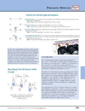
Two-Hand, No-Tie-Down ANSI
Circuit Restriction N-1 determines the time span during which both
signals must be received in order to obtain the output. When
V-1 V-2 RV-1 and RV-2 are actuated together, supply air is directed
push button push button through RV-1, RV-2 and RV-3 to the output, providing a
4 S S
momentary output signal that is determined by N-1. If a
4
N-1
maintained signal is required, a jumper between E and F
orifice
maintains an output as long as the operator is depressing
F
3 2
1 4 5 both palm buttons.
S 3 2 RV-3
7 8 1 1 R-315 E
RV-1 7 8 3 8 The indicator on RV-3 (R-315) must be down for an output
R-401 RV-2 2
output to be obtained. If either RV-1 or RV-2 is actuated separately,
R-401
their respective indicator will go up, but after approximately
one second, the indicator on RV-3 (R-315) will go down
showing that the valve has shifted and an output cannot be
Absolutely no alterations or modifications obtained. Circuit performance and sequence should be
should be made to this circuit or its
components parts. periodically observed to verify proper function.
Clippard Instrument Laboratory, Inc. 877-245-6247 www.clippard.com 246