Page 8 - Parker - Proportional Valves
P. 8

Catalog HY15-3502/US                              Proportional Relief Valve
                   Technical Information                             Series AP01B2YP 07C, 14C, 21C, 35C

            CV
                   General Description
                   Proportional Relief Valve. Increasing Pressure With
                   Increasing Current. For additional information see
            Valves
              Check
            SH     Technical Tips on pages PV1-PV6.


                   Features
            Valves
              Shuttle
            LM     •  Analog Proportional Relief Valve regulates pressure
                     proportionally to the solenoid current
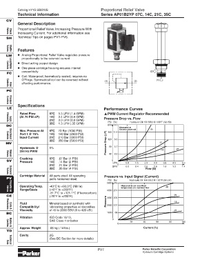
                   •  Direct acting poppet design
                   •  One piece cartridge housing ensures internal
            Controls
              Load/Motor
                     concentricity                                                                 (2)
            FC
                   •  Coil: Waterproof, hermetically sealed, requires no
                     O’Rings; Symmetrical coil can be reversed without                                 (1)
                                                                        (1)              (2)
                     affecting performance.
            Controls
              Flow
            PC

                   Specifications
              Pressure
            Controls
            LE                                                         Performance Curves
                    Rated Flow        07C   5.3 LPM (1.4 GPM)           PWM Current Regulator Recommended
                    (At 70 PSI ∆∆ ∆∆ ∆P)  14C  3.4 LPM (0.9 GPM)       Pressure Drop vs. Flow
                                      21C   3.0 LPM (0.8 GPM)
                                                                          PSI Bar      Hydraulic Oil 150 SSU @ 100°F (32 cSt)
              Logic
            Elements
                                      35C   1.3 LPM (.35 GPM)            200 14.3
            DC
                                                                                 Measured at
                                                                                 De-energized coil  -35
                    Max. Pressure At  07C   70 Bar (1000 PSI)            P)  160  11.4
                    Port 1 @ 75%      14C   140 Bar (2000 PSI)
                    Input Current     21C   210 Bar (3000 PSI)           120  8.6
              Directional
            Controls
                                      35C   350 Bar (5000 PSI)
            MV                                                           Pressure Drop (                 -21
                    Hysteresis @      5%                                  80  5.7                                  -07
                    200 Hz PWM                                            40  2.0                         -14
              Manual
            Valves
                    Cracking          07C   .07 Bar (1 PSI)
            SV      Pressure          14C   .14 Bar (2 PSI)                 0 LPM   0.8   1.5   2.3  3.0   3.8   4.5  5.3
                                      21C   .21 Bar (3 PSI)                    0
                                                                            GPM     0.2   0.4   0.6  0.8   1.0   1.2  1.4
                                      35C   .35 Bar (4 PSI)                                     Flow (Q)
              Solenoid
            Valves
                    Cartridge Material  All parts steel. All operating  Pressure vs. Input Signal (Current)
            PV                        parts hardened steel.
                                                                          PSI Bar      Hydraulic Oil 150 SSU @ 100°F (32 cSt)
                                                                         5000 345
                    Operating Temp.   -40°C to +93.3°C (Nitrile)                  Measured at coil stabilized  -35
                                                                                  temperature and nominal flow
                    Range/Seals       (-40°F to +200°F)                  4000  274
                                      -31.7°C to +121.1°C (Fluorocarbon)
            Valves
              Proportional
            CE                        (-25°F to +250°F)                  3000  205                                -21
                                                                         Pressure                                 -14
                    Fluid             Mineral-based or synthetic with    2000  137
                    Compatibility/    lubricating properties at viscosities
                    Viscosity         of 45 to 2000 SSU (6 to 420 cSt)                                            -07
              Coils &
            Electronics
            BC                                                           1000  68
                    Filtration        ISO Code 16/13,
                                                                            0
                                      SAE Class 4 or better                            20      40      60      80     100
                                                                               0
            Cavities
              Bodies &
                    Approx. Weight    .06 kg (.14 lbs.)                                        Current (%)
            TD
                    Cavity            2G
                                      (See BC Section for more details)
              Technical
            Data
                                                                    PV7                        Parker Hannifin Corporation
                                                                                               Hydraulic Cartridge Systems
   3   4   5   6   7   8   9   10   11   12   13