
Page 10 - Wago_Rail-MountedTerminalBlockSystems_Volume1_2015_US.pdf
P. 10
– Simply Push-In – S
1 Conductor Termination/Removal
8 Handling Ex e/Ex i Separators
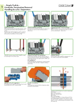
Tool-Free Terminations Stranded conductors with ferrules Conductor termination – Push-in connection
Stripped solid, ferruled or ultrasonically “bonded” conduc- from at least two sizes below the rated cross section up to Solid conductors with cross sections from either one size
tors are easily terminated by simply pushing them into a the rated cross section can also be simply pushed in – above, or up to two sizes below, the rated cross section
contact. without tools. can be inserted directly – without tools.
This advantage significantly reduces costs for conductors
rated 0.5 mm² to 16 mm² (AWG 20-4) in applications
such as electrical installations or factory wiring.
®
®
TOPJOB S features universal CAGE CLAMP S connec- Conductor termination with operating tool Conductor removal
tion technology for all conductor types. Connecting fine-stranded conductors without ferrules, or Like the original CAGE CLAMP an operating tool is used
®
small cross-sectional conductors that cannot be pushed in, for conductor removal with CAGE CLAMP S.
®
is performed similarly to the original CAGE CLAMP - just
®
use an operating tool.
The smart feature:
To open the clamp, the operating tool is inserted vertically.
The conductor entry is less than 15 degrees resulting in
easier wiring.
Separator for Ex e/Ex i applications Ex e II/Ex i terminal strip
An end plate must be applied to the terminal block located Notice:
directly behind an Ex e/Ex i separator plate. The movable feet of terminal blocks and separator plates
must face the same direction.
Separator located between Ex e II and Ex i terminal strip
! End plate
" Ex e II terminal blocks
? Ex e/Ex i separator plate
$ End plate
% Ex i terminal blocks
According to EN 50020, a minimum distance of 50 mm
must be kept between live parts of Ex e and Ex i circuits.
The use of Ex e/Ex i separators is a space-saving solution
when Ex e and Ex i terminal blocks are mounted on a com-
mon carrier rail.