
Page 241 - Wago_Rail-MountedTerminalBlockSystems_Volume1_2015_US.pdf
P. 241
"
Disconnect and Ground Conductor
Disconnect Terminal Blocks 5
239
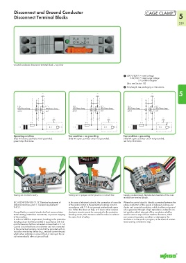
Ground conductor disconnect terminal block – top view
1 400 V/800 V = rated voltage
6 kV/8 kV = rated surge voltage
3 = pollution degree
(also see Section 14)
2 Strip length, see packaging or instructions.
5
H 2 H 1 H 2 H 1 H 2 H 1
LED/Neon lamp LED/Neon lamp LED/Neon lamp LED/Neon lamp LED/Neon lamp LED/Neon lamp
green red green red green red
F 1 F 1 F 1
T 1 K 2 K 1 T 1 K 2 K 1 T 1 K 2 K 1
Operating condition Test condition – no grounding Test condition – grounding
Slide link closed, auxiliary circuit grounded, Slide link open, auxiliary circuit not grounded. Slide link open, auxiliary circuit not grounded,
green lamp illuminates. red lamp illuminates.
Testing via conductor entry. Testing via or jumper contact position in current bar. Supply via disconnect. All-pole disconnection of the com-
moned fuse terminal blocks.
IEC 60204/DIN VDE 0113 “Electrical equipment of In the case of electronic circuits, the connection of one side Where the control circuit is directly connected between the
industrial machines, part 1: General requirements” of the control circuit to the protective bonding circuit in phase conductors of the supply or between a phase con-
9.4.3.1: accordance with 9.1.4 can prevent unintentional opera- ductor and a neutral conductor, which is either not ground-
tion. When this does not help, or if due to other reasons ed or grounded through a high impedance, multipole con-
Ground faults on control circuits shall not cause uninten- electronic circuits cannot be connected to the protective trol switches which interrupt all live conductors shall be
tional starting, hazardous movements, or prevent stopping bonding circuit, other measures shall be taken to achieve used for start or stop of those machine functions, which
of the machine. the same level of safety. can cause a hazardous condition or damage to the
In order to fulfill this requirement, bonding to the protective machine or to the work in progress, in the event of uninten-
bonding circuit shall be provided in accordance with 8.2 tional starting or failure to stop.
and the devices shall be connected as described in 9.1.4.
Control circuits fed from a transformer and not connected
to the protective bonding circuit shall be provided with an
insulation monitoring device (e.g., residual current device)
which either indicates an ground fault or interrupts the cir-
cuit automatically after an ground fault.