Page 447 - Wago_Rail-MountedTerminalBlockSystems_Volume1_2015_US.pdf
P. 447

9


                                                                                                                    445

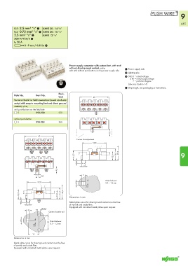
          0.5 - 2.5 mm² “s” 1  AWG 20 - 14 “s”                                  
          0.5 - 0.75 mm² “s” 1  AWG 20 - 18 “s”
          2.5 mm² “s” 2     AWG 12 “s”
          500 V/4 kV/2 3
          I N 20 A
          L 8 - 9 mm / 0.33 in 4


                                             Power supply connector with custom foot, with and
                                             without direct ground contact, white,   1 Power supply side
                                             with and without push-buttons on the power supply side
                                                                                2 Lighting side
                                                                                3 500 V = rated voltage
                                                                                   4 kV = rated surge voltage
                                                                                     2 = pollution degree
                                                                                  (also see Section 14)
                                                                                4 Strip length, see packaging or instructions.
                                      Pack.
          Pole No.      Item No.
                                      Unit          <___________ 40 ____________>
          Terminal block for field connection (round conductor
          entry) with snap-in mounting feet and direct ground
          contact, white,
          with push-buttons on the field side
            5           293-230       250
          without push-button
            5           293-228       250

                                                                       10 >
                 <____________ 40 ____________>                        <
                                                 Custom foot adjustment
                                                     <________  32,8 ________>
                                                                            ___> _>
                                                13,7_>                   _>  <___16,1  20,2                         9
                                                <_  <                    <_ 12,6  <___
                                                  >4,3
                                     4,5 <         > 4,9 <
                                     >
                      > 4,4  <_ 2,8                > 5  <
                       >  <__
                  <________ 32,8 ________>        <      <          Plate thickness:
                                                                    0.5 – 1.2 mm
                                         ___>     > 4,6  2,8  __>
             _>                        _>  20,2
             <_13,7  <                <_ 12,6_>  <___16,1  <___  Dimensions in mm

               >4,3                            Metal plate cutout for direct ground contact must be free
                > 4,9  <                     of varnish and oxide films.
                           Ø 3,5             Equipped with varnished metal plates upon request.
                > 5  <  >  <____  Center of carrier rail

               <        <       ___>
               > 4,6            20  Plate thickness:
                       2,8  __>  <____ 0.5 – 1.2 mm


                   <__15 __>
          Dimensions in mm

          Metal plate cutout for direct ground contact must be free
          of varnish and oxide films.
          Equipped with varnished metal plates upon request.
   442   443   444   445   446   447   448   449   450   451   452