
Page 457 - Wago_Rail-MountedTerminalBlockSystems_Volume1_2015_US.pdf
P. 457
" 10
455
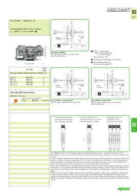
0.2 - 6 mm² AWG 24 - 10
Terminal block width 16 mm / 0.63 in
H 2 H 1
L 12 - 13 mm / 0.49 in 2 LED/Neon lamp LED/Neon lamp
green red
Test socket
Jumper riveted
connection
F 1
T 1 K 2 K 1
< 38,5 mm/1.52 in > Operating condition 1 400 V = rated voltage
6 kV = rated surge voltage
Slide link closed, auxiliary circuit grounded,
3 = pollution degree
green lamp illuminates.
(also see Section 14)
2 Strip length, see packaging or instructions.
3 See application notes for:
<____________ 87,5 mm/3.44 in ____________> Test plug module, page 291
Pack.
Item No.
Unit
Ground conductor disconnect terminal block, gray
24 V 282-140 12 H 2 H 1 H 2 H 1
48 V 282-141 12 LED/Neon lamp LED/Neon lamp LED/Neon lamp LED/Neon lamp
120 V 282-138 12 green red green red
230 V 282-139 12 Jumper Test socket Jumper Test socket
riveted
riveted
connection connection
F 1 F 1
Item-Specific Accessories
T 1 K 2 K 1 T 1 K 2 K 1
Lock-out, snap-in type,
prevents reclosing of slide link
orange 282-137 100 (4x25) Test condition – no grounding Test condition – grounding
Slide link open, auxiliary circuit not grounded. Slide link open, auxiliary circuit not grounded,
red lamp illuminates.
Current transformer circuit Current transformer circuit Transformer test circuit,
with current path separation with the connection of a second k-conductors of the
and commoning possibility test unit through test sockets transformers connected
10
l kl kl k
IEC 60204/DIN VDE 0113 “Electrical equipment of industrial machines, part 1: General requirements” 9.4.3.1:
Ground faults on control circuits shall not cause unintentional starting, hazardous movements, or prevent stopping of the
machine.
In order to fulfill this requirement, bonding to the protective bonding circuit shall be provided in accordance with 8.2 and
the devices shall be connected as described in 9.1.4. Control circuits fed from a transformer and not connected to the
protective bonding circuit shall be provided with an insulation monitoring device (e.g., residual current device) which
either indicates an ground fault or interrupts the circuit automatically after an ground fault.
In the case of electronic circuits, the connection of one side of the control circuit to the protective bonding circuit in accor-
dance with 9.1.4 can prevent unintentional operation. When this does not help, or if due to other reasons electronic cir-
cuits cannot be connected to the protective bonding circuit, other measures shall be taken to achieve the same level of
safety.
Where the control circuit is directly connected between the phase conductors of the supply or between a phase conduc-
tor and a neutral conductor, which is either not grounded or grounded through a high impedance, multipole control
switches which interrupt all live conductors shall be used for start or stop of those machine functions, which can cause a
hazardous condition or damage to the machine or to the work in progress, in the event of unintentional starting or failure
to stop.