
Page 38 - Parker - Rodless Air Cylinders
P. 38
Catalog #AU03-0928/NA Rodless Air Cylinders
Shock Absorbers P1X Series
Selection Criteria
The Shock Absorber Advantage
• Increase equipment throughput • Prevents impact damage
• Smoother deceleration of loads • Minimize shock loads on equipment
• Adjustable end of stroke positioning • Improves product performance
Four Steps to Great Performance
Step 1. Gather the Application Parameters Step 3. Verify the Cycle Rate
• Total load weight (pounds) • See shock specifications below and
verify application is within cycle rate
• Final velocity at impact (inches/second)*
• Cycle rate (cycles per hour) Step 4. Choose the Appropriate Option in
Model Code
Step 2. Verify Shock Absorber Performance
• See charts on the following pages
• Determine that shock absorber will so the job
*If final velocity cannot be easily calculated, double the average velocity.
Shock Absorber Specifications
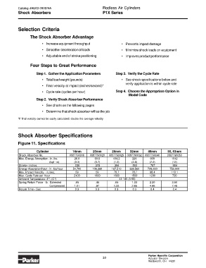
Figure 11. Specifications
Cylinder 16mm 20mm 25mm 32mm 40mm 50, 63mm
Shock Absorber No. 0887790016 0887790020 0887790025 0887790032 0887790040 0887790050
Max. Energy Absorption - in.-lbs. 26.0 60.8 104.2 226 608 1042
(kgf · m) (0.3) (0.7) (1.2) (2.6) (7.0) (12)
Stroke - inches .236 .315 .394 .590 .787 .984
Energy Absorption/hour - in.-lbs/hour 54,700 109,380 187,510 338,560 729,200 750,000
Max. Impact Velocity - in./sec. 59 59 78.7 78.7 98.4 118.1
Max. Cycle Rate per Hour 2100 1800 1800 1500 1200 720
Ambient Temperature - F°, (C°) 41-140 (5-60)
Spring Return Force - lb. Extended .65 .45 .65 1.33 2.20 3.60
Compressed 1.01 .97 1.33 2.65 4.86 7.49
Return Time - Sec. 0.3 0.3 0.3 0.3 0.4 0.4
Parker Hannifin Corporation
30 Actuator Division
Wadsworth, OH 44281