Page 51 - Parker - Rodless Air Cylinders
P. 51

Catalog #AU03-0928/NA                             Rodless Air Cylinders
            Mountings / Load and Deflection                   P1Y Series


            Figure 13 shows the maximum allowable moments for   Figure 14
            each of the three types of loading: Bending, Radial, and
            Cross moments.                                                 Max. Allowable     Max. Unsupported
                                                                          Load [L] N (Lbs)
            The sum total of each of these types of moments, divided by  Bore                   Length mm (in)
            each of the maximum values, determines a Load-Moment         Single     Double       at Max. Load
            Factor (LMF) should be equal to or less than 1.0. On        Carriage   Carriage
            horizontal mountings, the total load (L) should also be  25  289 (65)  578 (130)      1015 (40)
            divided by the maximum load allowable (Figure 14) and  32   534 (120)  1068 (240)     1140 (45)
            factored into the equation.                           40    800 (180)  1600 (360)      915 (36)
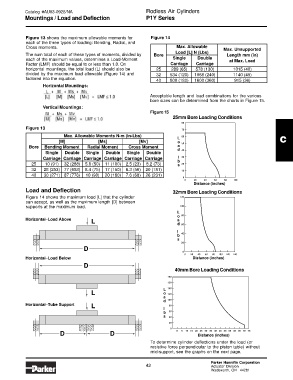
                   Horizontal Mountings:
                                                                Acceptable length and load combinations for the various
                                                                bore sizes can be determined from the charts in Figure 15.
                   Vertical Mountings:
                                                                Figure 15
                                                                         25mm Bore Loading Conditions
                                                                             80
            Figure 13                                                        70
                            Max. Allowable Moments N-m (In-Lbs)              60
                                                                           L                                          C
                          [M]             [Ms]             [Mv]            o
                                                                             50
             Bore   Bending Moment    Radial Moment    Cross Moment        a
                                                                           d  40
                    Single   Double   Single   Double   Single   Double
                   Carriage Carriage Carriage Carriage Carriage Carriage   l  30
                                                                           b
              25    10 (91)  32 (288)  5.6 (50)  11 (100)  2.5 (23)  8.2 (73)  s  20
              32   28 (253) 77 (688)  8.4 (75)  17 (150)  6.3 (56)  20 (181)  10
              40   30 (271) 87 (776)  10 (90)  20 (180)  7.6 (68)  26 (231)
                                                                             0
                                                                              0   20  40  60   80  100
                                                                                  Distance (inches)
            Load and Deflection                                          32mm Bore Loading Conditions
            Figure 14 shows the maximum load [L] that the cylinder          120
            can accept, as well as the maximum length [D] between
            supports at the maximum load.                                   100
                                                                           L
                                                                           o  80
            Horizontal–Load Above                                          a
                                       L
                                                                           d 60
                                                                           l
                                                                           b  40
                                                                           s
                                                                             20
                                    D
                                                                             0
                                                                              0  20  40  60  80  100  120  140
            Horizontal–Load Below                                                 Distance (inches)
                                    D
                                                                          40mm Bore Loading Conditions
                                                                       180
                                                                       160
                                                                     L  140
                                       L                             o  120
                                                                     a
                                                                     d  100
            Horizontal–Tube Support    L                                80
                                                                     l
                                                                     b  60
                                                                     s  40
                                                                        20
                                                                        0
                                                                           0  5  10 15 20 25 30 35 40 45 50 55 60 65 70 75
                          D                    D                                    Distance (inches)
                                                                To determine cylinder deflections under the load (or
                                                                resistive force perpendicular to the piston table) without
                                                                mid-support, see the graphs on the next page.

                                                                                         Parker Hannifin Corporation
                                                              43                         Actuator Division
                                                                                         Wadsworth, OH  44281
   46   47   48   49   50   51   52   53   54   55   56