
Page 52 - Parker - Rodless Air Cylinders
P. 52
Catalog #AU03-0928/NA Rodless Air Cylinders
Load and Deflection P1Y Series
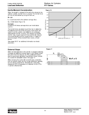
Inertia Moment Consideration Figure 16
When the weight is stopped at the end of the stroke by the 40
cylinder cushion, inertial force is created. This inertial force
(Fi) can be determined by using the formula: 35
Fi = LG 30
L= Load attached to the cylinder carriage (lbs.) 25
G = Inertia factor (Figure 16)
Example: INERTIA FACTOR (G) 20
A speed of 40 in/sec corresponds to an inertia factor
G of 13. 15
The inertial force calculated would then be multiplied by 10
the distance from the center of gravity of the load to the
centerline of the cylinder, and added to the previously 5
calculated M and Mv moments. This will give an M Total
and Mv Total. Ensure that the M Total and the Mv Total do
not exceed the [M] and [Mv] values shown in Figure 13
20 40 60 80
(previous page). If they exceed these values, consult
SPEED (IN PER SEC) (V)
factory.
See pages 50-51 for additional information on shock
absorbers.
External Stops Figure 17
When the load attached to the cylinder is stopped externally,
it creates an additional moment equal to the cylinder actual Fa
force (Fa) times the distance (S). This additional moment,
plus the previously calculated Load-Moment factor, should
not exceed the allowable values. See page 41.
S M= F x S
a
When reducing the stroke with external stops, remember
that the cushion length and the energy absorption capacity
are not directly proportional. Reducing the cushioning
distance by 50% corresponds to a reduction of 60 to 70%
in cushion effectiveness.
Parker Hannifin Corporation
44 Actuator Division
Wadsworth, OH 44281