
Page 9 - Parker - Rodless Air Cylinders
P. 9
Catalog #AU03-0928/NA Sizing Guidelines
Application Guide Rodless Cylinders
Sizing Guide for Rodless Cylinders
Introduction
Unlike traditional cylinders with piston rods, where A
load forces are normally experienced on the cylinder
centerline, the design of rodless cylinders dictates
that all load forces are eccentric to some degree.
Depending on the application, these eccentric load
forces can become quite substantial and create
an adverse effect on cylinder performance and
life expectancy. As a result, the use of rodless
cylinders, and the manner in which they are
designed into a system, requires careful consider- Figure 1
ation of a variety of engineering factors to ensure
optimal performance. These factors include load
moments, mounting method, total weight, resistive
force, velocity and deceleration.
Note: Parker Application Engineers will be happy to Bending Moment M (Pitch)
assist you in evaluating your application. For your
convenience, there are typical application loading
diagram forms on pages 6-9 which show the three
basic cylinder mounting conditions:
Condition 1 - Cylinder horizontal, Carriage horizontal
Condition 2 - Cylinder horizontal, Carriage vertical
Radial Moment Ms (Roll)
Condition 3 - Cylinder vertical, Carriage vertical
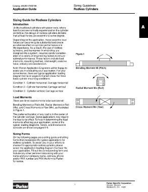
Load Moments
There are three load moments to be considered:
Bending Moment or Pitch (M), Radial Moment or Roll
(Ms), and Cross Moments or Yaw (Mv), as illustrated Cross Moment Mv (Yaw)
in Figure 1.
The preferred location of any load is in the center of
the cylinder carriage. Some applications may require
the load to be offset. To help in determining the load
moments affecting your application, some of the
typical loading diagrams, forces, and distances to
consider are shown on pages 6-9.
Sizing Forms
On the following pages are a sizing guide and sizing
forms that incorporate the typical applications for
rodless cylinders. To assist you in your efforts to
choose the appropriate rodless cylinder, please
select the application loading diagram that best fits
your application. Fill out the corresponding form and
include any other pertinent data along with your
name and your company name, address, phone
and/or FAX number and FAX the form to Parker
for review.
Parker Hannifin Corporation
1 Actuator Division
Wadsworth, OH 44281